
Stator foar aspiration motor, aspiration motor and in-car sensor using the same

a technology which is applied in the direction of instruments, horology, magnetic circuit shape/form/construction, etc., can solve the problems of poor starting phenomenon of aspiration motor, difficult to set up an accurate direction and position of back yoke b>5/b> and the hall element, and reduce the manufacturing cost of aspiration motor and stator using the same. , to achieve the effect of enhancing productivity, reducing the cost o

Active Publication Date: 2012-12-25
AMOTECH
View PDF21 Cites 0 Cited by
  • Summary
  • Abstract
  • Description
  • Claims
  • Application Information

AI Technical Summary

Benefits of technology

The present invention relates to a stator for an aspiration motor used in an in-car sensor. The invention simplifies the manufacturing process of the stator, improves productivity, and reduces costs. The technical effects of the invention include reducing the likelihood of inferiority and improving the efficiency of the manufacturing process. The invention also addresses the issue of positioning the back yoke and hall element accurately to prevent starting issues of the aspiration motor. Additionally, the invention simplifies the connection between the stator coil and control printed circuit board, and reduces the likelihood of damage to the stator coil during assembly.

Problems solved by technology

By the way, since the position detection hall element is expensive, the conventional brushless direct-current (BLDC) motor employs a drive circuit having only one position detection hall element.
Otherwise, the hall element cannot detect polarity of the magnet 4a, due to the dead point, to thus cause a bad starting phenomenon of the aspiration motor.
As a result, it is difficult to set up an accurate direction and position of the back yoke 5 and the hall element.
As a result, a manufacturing cost of the conventional aspiration motor is risen.
As a result, the processes of manufacturing the stator 10 are very complicated.
As a result, accuracy of an assembly process drops, and productivity is also lowered.
As a result, an inferiority increases at the time of manufacturing aspiration motors.

Method used


Image

  • Stator foar aspiration motor, aspiration motor and in-car sensor using the same
  • Stator foar aspiration motor, aspiration motor and in-car sensor using the same
  • Stator foar aspiration motor, aspiration motor and in-car sensor using the same

Examples


Embodiment Construction

]

[0142]As described above, the present invention has been described with respect to particularly preferred embodiments. However, the present invention is not limited to the above embodiments, and it is possible for one who has an ordinary skill in the art to make various modifications and variations, without departing off the spirit of the present invention. Thus, the protective scope of the present invention is not defined within the detailed description thereof but is defined by the claims to be described later and the technical spirit of the present invention.

[Industrial Applicability]

[0143]As described above, the present invention can be applied to a stator for an aspiration motor, an aspiration motor and an in-car sensor using the same, in which an inexpensive insulation wire can be used to thus manufacture a stator at low cost, and a bearing seat, a back yoke and a hall element are integrally injection-molded in an insert-molding method, to thus simplify a manufacturing proces...


PUM


Abstract

Provided are a stator for an aspiration motor, an aspiration motor and an in-car sensor using the same, in which a bobbin is integrally formed with a stator, to thus use an inexpensive insulation wire and enhance a productivity and lower an inferiority using an insert-molding technology. The stator for the aspiration motor includes a stator support plate, a support boss which is vertically extended from the central portion of the stator support plate, a bobbin which is bent and formed on the lateral surface of the support boss, and which is separated from the upper side surface of the stator support plate, to thereby provide a space, and a stator coil which is formed by making a wire wound in the space provided by the bobbin.

Description

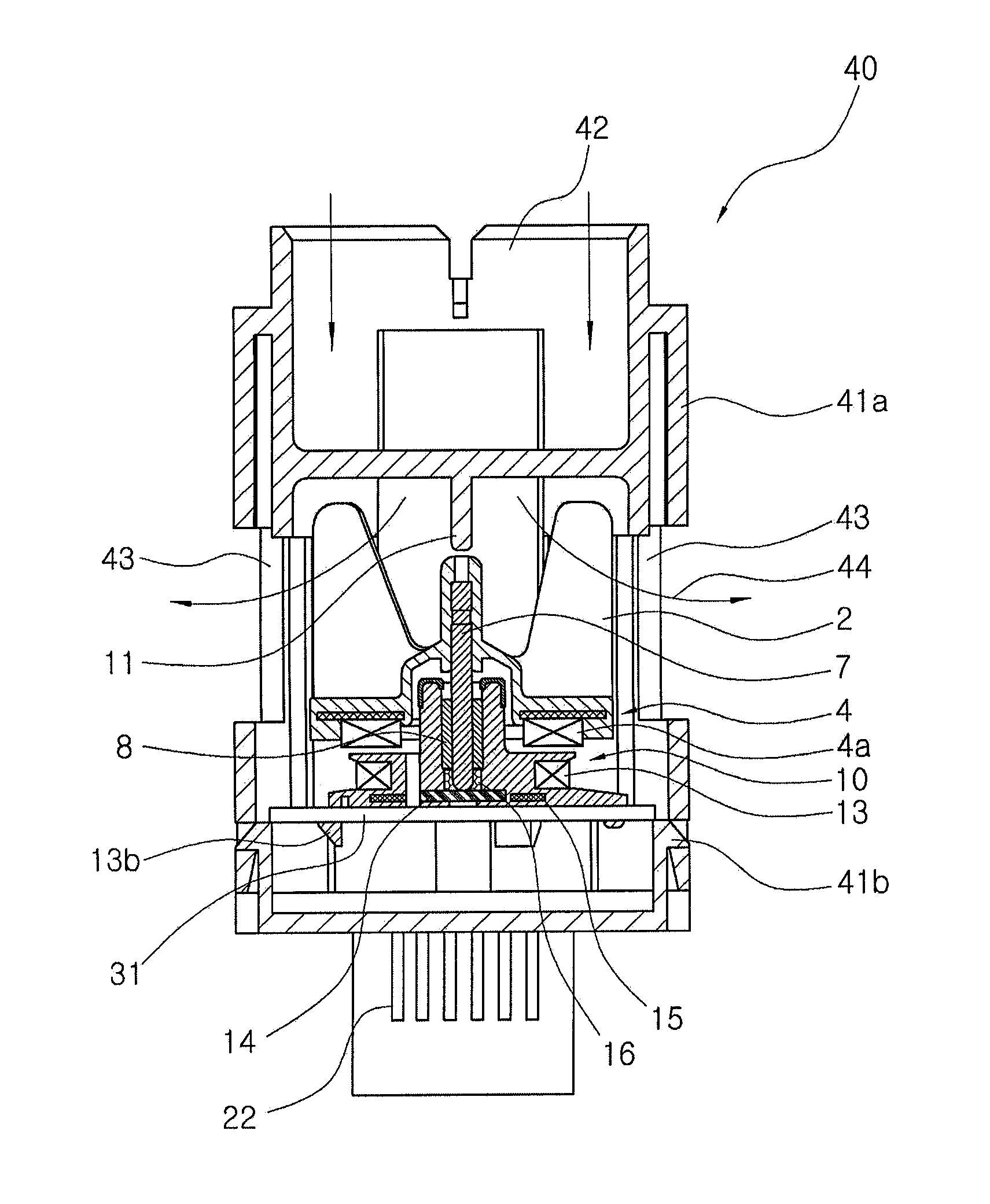
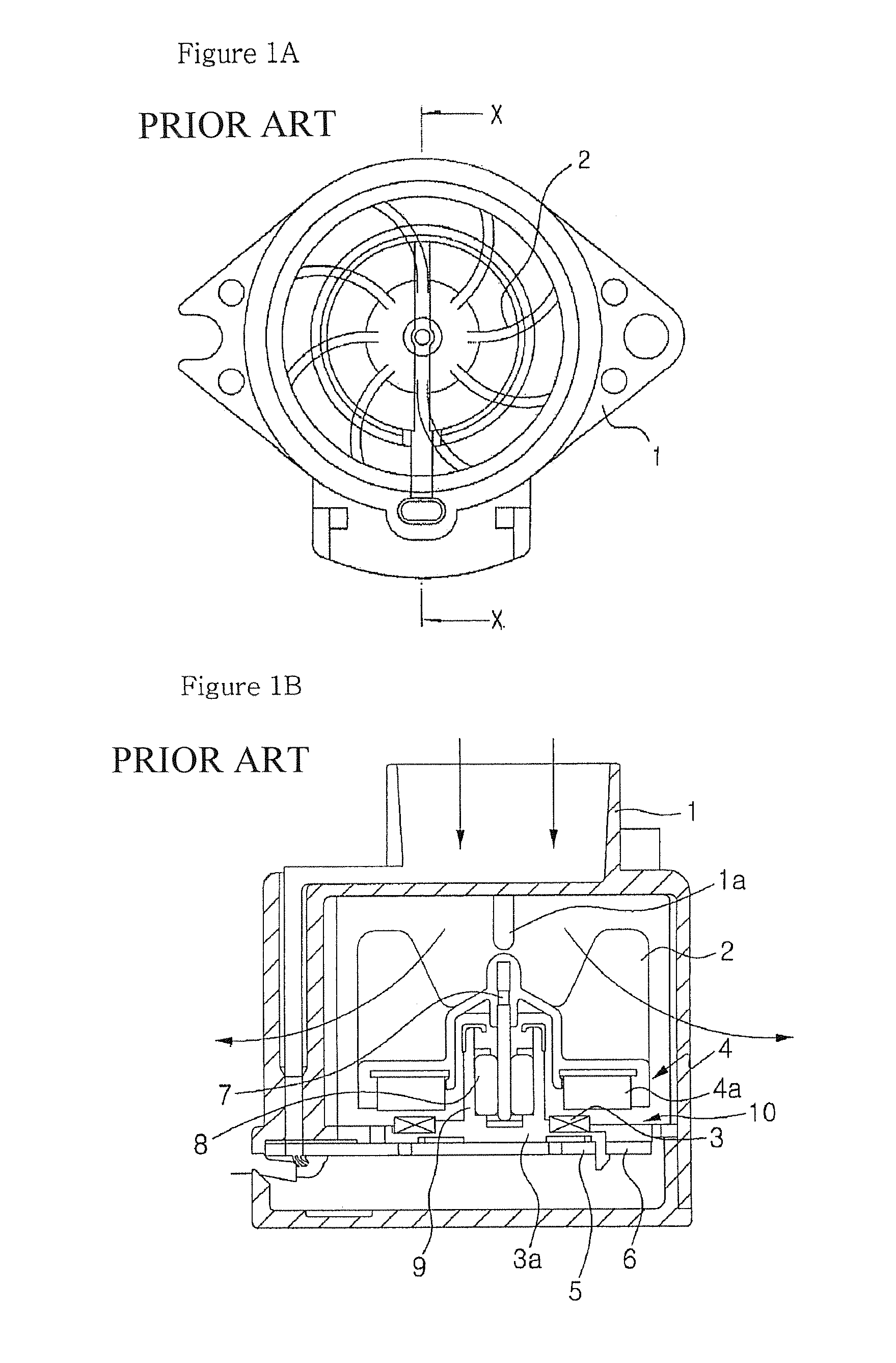
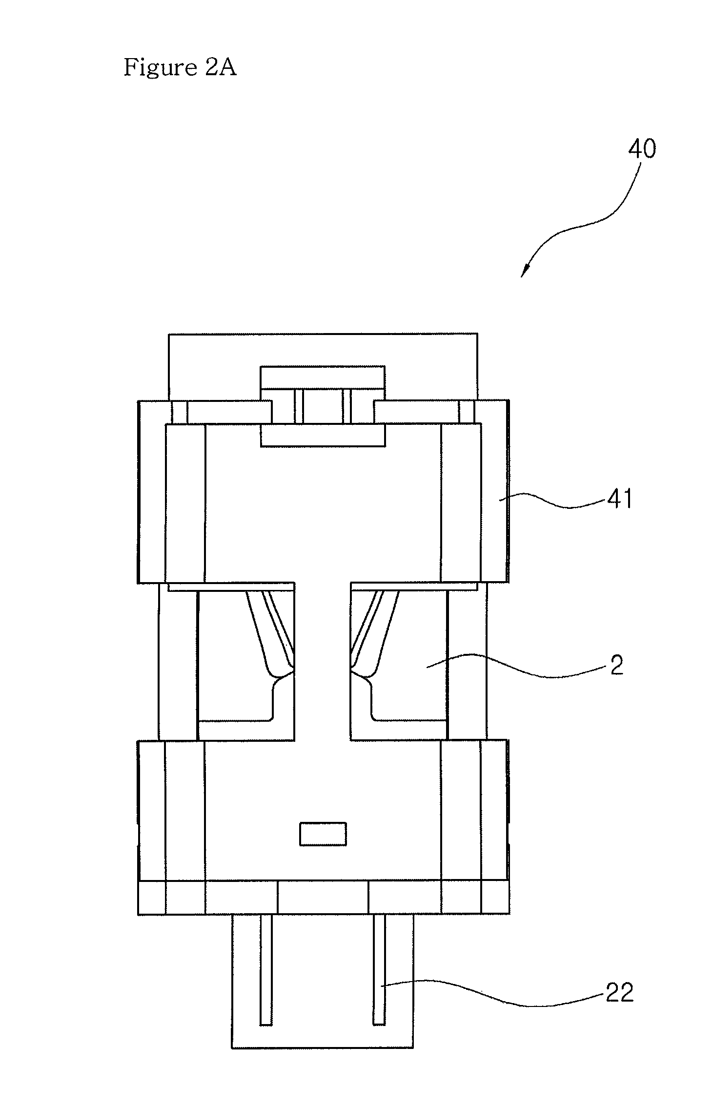
TECHNICAL FIELD[0001]The present invention relates to a stator for an aspiration motor, an aspiration motor and an in-car sensor using the same, and more particularly, to a stator for an aspiration motor, an aspiration motor and an in-car sensor using the same, in which processes which are apt to raise an inferiority and lower productivity are simplified in a method of manufacturing a stator for a motor, to thereby enhance productivity, while causes which increase an inferiority are solved, to thereby lower an inferiority and to lower a productive unit cost.BACKGROUND ART[0002]In general, an in-car sensor is provided to measure indoor temperature in a car similarly to the purpose of providing a car indoor ventilator. The in-car sensor is installed in the rear surface of a grill or an instrument panel of the car. The in-car sensor employs an aspiration motor in order to inhale indoor air in the car.[0003]FIG. 1A is a plan view of a general aspiration motor, and FIG. 1B is a cross-sec...

Claims


Application Information

Patent Timeline
Patent Type & Authority Patents(United States)
IPC IPC(8): H02K1/00H02K3/00H02K19/26H02K21/00H02K23/40
CPCH02K3/46H02K7/14H02K11/0015H02K11/0047H02K21/24H02K2211/03H02K3/47H02K11/21H02K11/25H02K1/12
Inventor KIM, BYOUNG KYUKIM, BYOUNG SOO
Owner AMOTECH
Learn More