Antenna mount

a satellite antenna and antenna technology, applied in the field of satellite communications, can solve the problems of increasing material cost and assembly tim

Inactive Publication Date: 2012-12-25
AZURE SHINE INT
View PDF3 Cites 36 Cited by
  • Summary
  • Abstract
  • Description
  • Claims
  • Application Information

AI Technical Summary

Problems solved by technology

Such connection, however, may require several sets of bolts and nuts, which may inevitably incur an increase in material cost and assembly time.

Method used


Image

  • Antenna mount
  • Antenna mount
  • Antenna mount

Examples


Embodiment Construction

[0019]Reference will now be made in detail to the present examples of the invention illustrated in the accompanying drawings. Wherever possible, the same reference numbers will be used throughout the drawings to refer to the same or like portions.

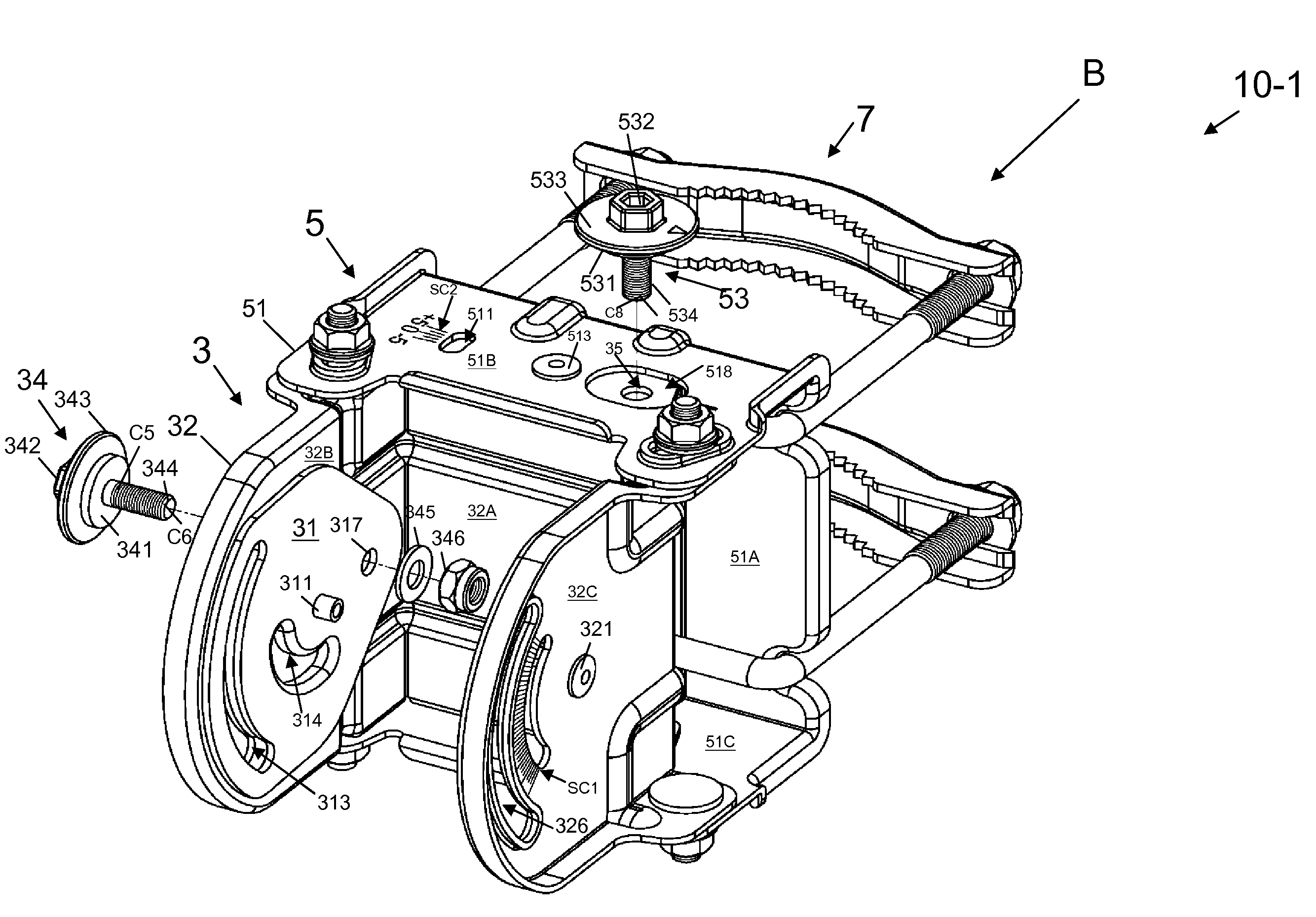
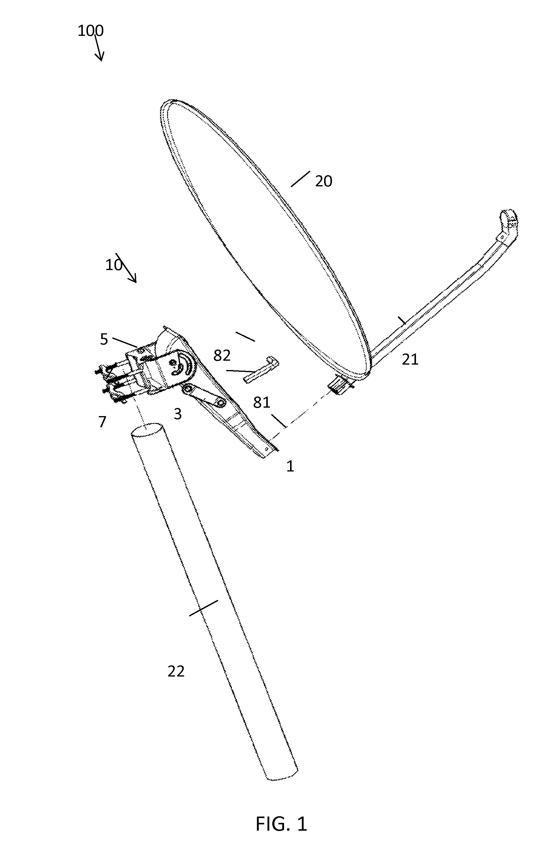
[0020]FIG. 1 is a perspective view of a satellite antenna 100 in accordance with an example of the present invention. Referring to FIG. 1, the satellite antenna 100 may include an antenna mount 10 and an antenna dish 20. Moreover, the antenna mount 10 may include a connecting member 1, an elevation adjustment member 3, an azimuth adjustment member 5 and a clamp 7. The connecting member 1 may be adapted to couple with a connecting arm 21 of the satellite antenna 100. The clamp 7 may be adapted to secure the antenna mount 10 to a mounting pole 22. The elevation adjustment member 3 and the azimuth adjustment member 5 may be respectively adjusted in elevation angle and azimuth angle by using a wrench, for example, an open-end wrench 81 or a box...


PUM


Abstract

An antenna mount for a satellite antenna comprises an adjustment plate with a first cam slot, a first bracket and a first cam. The first bracket includes a first base, a first sidewall extending from the first base and having a second cam slot aligned with the first cam slot, and a second sidewall extending in parallel with the first sidewall from the first base. The first cam is adapted to attach the adjustment plate to an inner surface of the first sidewall. The first cam includes a first shaft protruding from the first sidewall through the first and second cam slots and rotatable with respect to the first sidewall, and a first disc coupled with the first shaft and adapted to fit within the first cam slot so that the adjustment plate is rotatable with respect to the first sidewall as the first shaft is rotated from the exterior of the first sidewall.

Description

TECHNICAL FIELD[0001]The present invention relates generally to satellite communications and, more particularly, to an antenna mount for a satellite antenna.BACKGROUND[0002]Thanks to the rapid development of satellite technology, high-speed data transmission for long-range communications is feasible nowadays. For optimal performance, it may be necessary for a satellite antenna to be precisely aligned with a target signal source. Alignment of a satellite antenna may generally be performed via an adjustable antenna mount, in which a movable connection is typically incorporated. The movable connection may include, for example, one or more cam(s) along with a number of slots for antenna mount adjustment. In some antenna mounts, as one disclosed in U.S. Pat. No. 7,439,930 to Bury, a cam structure may be coupled with a stationary member such as a bracket of the antenna mount by fastening connection. Such connection, however, may require several sets of bolts and nuts, which may inevitably...

Claims


Application Information

Patent Timeline
Patent Type & Authority Patents(United States)
IPC IPC(8): H01Q1/12H01Q3/02
CPCH01Q1/125H01Q3/02
Inventor SHEN, WEN-CHAO
Owner AZURE SHINE INT
Why Eureka
Try Eureka