SOI-MEMS gyroscope having three-fold symmetry

a gyroscope and three-fold technology, applied in the field of gyroscopes, can solve the problems of large vibration environment, low sensitivity of the device, and inability to meet the demanding and challenging requirements of military combat systems, so as to maximize the dynamic range, reduce the effect of vibration and reduce the error ra

Inactive Publication Date: 2007-09-11
UNITED STATES OF AMERICA THE AS REPRESENTED BY THE SEC OF THE ARMY
View PDF4 Cites 18 Cited by
  • Summary
  • Abstract
  • Description
  • Claims
  • Application Information

AI Technical Summary

Benefits of technology

[0040]Then x-axis oriented actuators are excited in one mode, rotations of the device about the z-axis result in oscillations in the orthogonal mode that are detected by y-axis oriented sensors. The mode-decoupled suspension allows only one degree of in-plane freedom for each excitation actuator, thereby attenuating errors due to oscillation axis misalignment.
[0041]In addition, suspension symmetry maintains matched oscillation mode frequencies through process and temperature variations, allowing maximized dynamic range in a wide dynamic range discrete-time control loop.
[0042]The three-fold symmetric gyroscope implementation inherently matches the resonant frequencies in both oscillation modes by using completely symmetric suspens

Problems solved by technology

Although these gyroscope technologies meet most inertial requirements, they tend to be moderately expensive.
Although many organizations are developing MEMS gyroscopes for a variety of applications, most do not begin to address the demanding and challenging requirements for military combat systems.
Furthermore, actuators in the control system of the guided munition may result in a substantial vibration environment.
The criteria for achieving superior resolution while measuring large rotation rate adds difficulty to design determination since there are tradeoffs that exist in determining the mechanical structure's topology.
For example, achieving superior resolution requires sub

Method used


Image

  • SOI-MEMS gyroscope having three-fold symmetry
  • SOI-MEMS gyroscope having three-fold symmetry
  • SOI-MEMS gyroscope having three-fold symmetry

Examples


Embodiment Construction

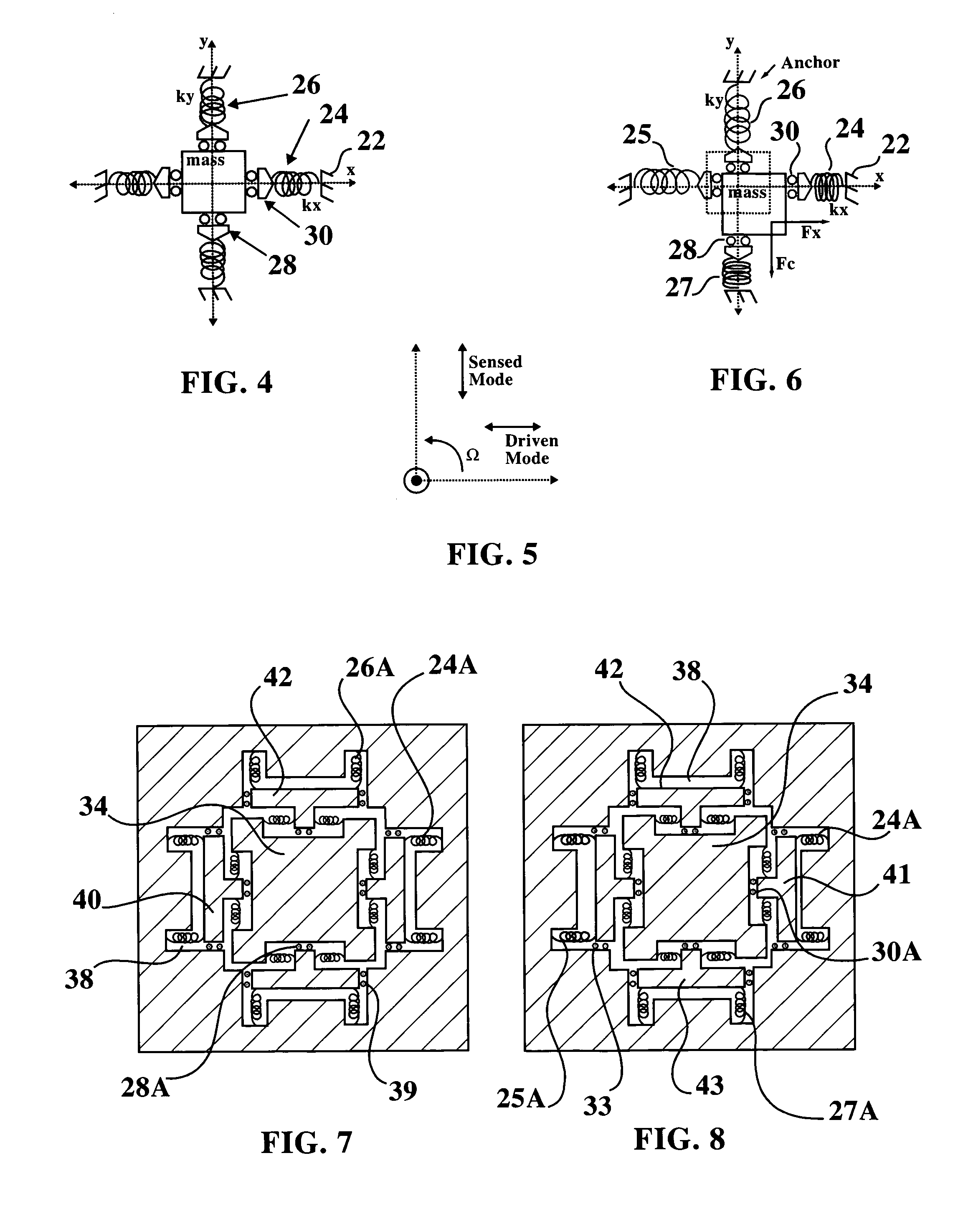
[0072]In a vibratory gyroscope, the two fundamental modes of oscillation are along the x-axis, the driven mode, and along the y-axis, the sensed mode (FIG 5).

[0073]A conceptual suspension, shown in schematic form in FIG. 4, approximates a set of identical springs 26, 24 placed symmetrically about a central mass. The springs 26, 24 are connected to respective rolling pins 28 and 30 that allow the mass to move and slide in the y and x directions.

[0074]In FIG. 6, the actual deflection of the mass in x and y is shown. The rolling pins 28, 30 constrain the springs to act along the x-axis or the y-axis, only. In that the mass of FIG. 6 has moved to the right and downward from its position in FIG. 4, the spring 24 is compressed against anchor 22. Spring 27 is likewise compressed from the mass' movement in the y direction while springs 26 and 25 are stretched. FIGS. 4 and 6 demonstrate that the restoring forces on the mass are always orthogonal and in line with the x- and y-axes.

[0075]In an...


PUM


Abstract

A SOI-MEMS gyroscope has a three fold symmetrical construction such that is symmetrical in the x direction, the y direction and diagonally. The gyroscope is suspended above a silicon substrate by lateral flexures that are located at the corners of the proof mass and by central flexures that are positioned at the center regions of the proof mass. The proof mass, lateral flexures, and central flexures are formed of a silicon composition with the flexures supporting the proof mass such that the proof mass will not touch the underlying base silicon substrate even when subjected to extreme G forces. Comb finger actuators apply an electrostatic force to the proof mass in the x direction; and, when experiencing an external rotational rate around the z-axis, the Coriolis force acts along the y direction and the resulting deflection is sensed by a pair of comb-finger capacitors connected as a differential capacitive voltage divider.

Description

DEDICATORY CLAUSE[0001]The invention described herein may be manufactured, used and licensed by of for the U.S. Government for governmental purposes without payment of any royalties thereon.BACKGROUND OF THE INVENTION[0002]I. Field of the invention[0003]The present invention relates to gyroscopes.[0004]More particularly, the present invention incorporates a stationary three-fold symmetric vibratory rate gyroscope implementation provided on a thick-film silicon-on-insulator (SOI), micro electro-mechanical system (MEMS).[0005]II. Discussion of the Background[0006]Small, affordable, and reliable inertial components are required for small diameter precision-guided military weapon systems. Gyroscopes are inertial components or devices that can sense angular rotation and / or rotation rate. The ring laser and interferometric fiber optic gyroscopes dominate the current tactical missile system market. Although these gyroscope technologies meet most inertial requirements, they tend to be moder...

Claims


Application Information

Patent Timeline
IPC IPC(8): G01P9/04
CPCG01C19/5719
Inventor KRANZ, MICHAEL S.HOLT, SHERRIE BURGETT
Owner UNITED STATES OF AMERICA THE AS REPRESENTED BY THE SEC OF THE ARMY
Why Eureka
Try Eureka