Split stabilizer and process for establishing a toothed connection of the outer rotary part to one of the two stabilizer parts

a technology of stabilizer and rotary part, which is applied in the direction of couplings, manufacturing tools, transportation and packaging, etc., can solve the problems of unsuitable vehicles, complicated manufacturing technology of individual parts, and further increase of manufacturing technological difficulties, so as to simplify the design of the connection

Inactive Publication Date: 2007-04-17
ZF FRIEDRICHSHAFEN AG
View PDF29 Cites 18 Cited by
  • Summary
  • Abstract
  • Description
  • Claims
  • Application Information

AI Technical Summary

Benefits of technology

[0012]The basic object of the present invention is therefore to simplify the design of the connection of the actuator to the corresponding stabilizer part. In terms of the process, the connection in question must be able to be established more simply and inexpensively compared with the prior-art manufacturing process.
[0018]Thus, the novel connection is characterized by high load-bearing capacity, which is due primarily to the teeth manufactured in such a way as to eliminate clearance. This load-bearing capacity is further increased by the circumferential weld seam, because the weld seam also assumes a load-bearing function to a limited extent. The absence of clearance of the teeth is so substantial or complete that the weld seam does not assume the torque transmission alone during any phase of its function. As a result, the requirements imposed on the strength of the weld seam can be kept low.
[0019]The circumferential weld seam thus designed has the advantage that it seals the teeth so hermetically that no pressurized medium can escape from the inner working chambers to be outside. The conventional sealing elements between the closing cover of the outer rotary part and the stabilizer part in question become unnecessary due to this sealing function, which leads to considerable cost savings. Furthermore, this weld seam secures the stabilizer part in relation to the closing cover of the outer rotary part against axial load. The radial pinning, which is otherwise necessary, and the difficult manufacture of the pin can thus be done away with, which likewise leads to cost savings. Moreover, weakening of the material due to the pinning in the closing cover and in the stabilizer part is avoided, which has a favorable effect on the load-bearing capacity of the connection.
[0020]It is particularly advantageous for the weld seam to be formed in an inner annular space. This is favorable in terms of the manufacturing technology and makes the weld seam invisible, so that it does not need to be subjected to cosmetic finishing.
[0021]Using non-weldable or only conditionally weldable materials, it is necessary, in order to avoid cracking, to perform a specific preheating and a defined cooling. It is advantageous in this connection to perform the preheating by induction annealing, because only a very limited area is thus heated, and to subsequently weld under protective gas, because this is a simple and inexpensive method.

Problems solved by technology

They are therefore unsuitable for vehicles that are designed for both the road and terrain.
This design solution leads to individual parts that are complicated in terms of manufacturing technology because the stabilizer part has a curved shape and a great length.
The manufacturing technological difficulties are further increased, especially in the case of the stabilizer part with the cover, by the fact that the end of the complicated stabilizer part must be processed by forming to manufacture the cover.
Such a welded connection does not meet the requirements imposed on the strength for the transmission of the high and varying torques because the stabilizer part consists of spring steel and the cover of a case-hardened material and, in particular, spring steel is not considered to be weldable.
The high welding temperatures lead to cracking during the phase of cooling.
In addition, laser beam welding is ruled out for cost reasons because a special laser welding machine with complicated devices becomes necessary for it.
Such teeth are, however, usually subject to a clearance due to the manufacturing technology, which is functionally manifested as a slip between the two rotary parts.
Such teeth are also not secured axially, so that a radial pin must be additionally inserted, and this pin further reduces the material thickness of the torque-transmitting parts, on the one hand, and is difficult to machine because of the high quality of the material, on the other hand, and it needlessly increases the manufacturing costs.
Another drawback is that the teeth do not guarantee sealing toward the outside.
This also makes the stabilizer more expensive.

Method used


Image

  • Split stabilizer and process for establishing a toothed connection of the outer rotary part to one of the two stabilizer parts
  • Split stabilizer and process for establishing a toothed connection of the outer rotary part to one of the two stabilizer parts
  • Split stabilizer and process for establishing a toothed connection of the outer rotary part to one of the two stabilizer parts

Examples


Embodiment Construction

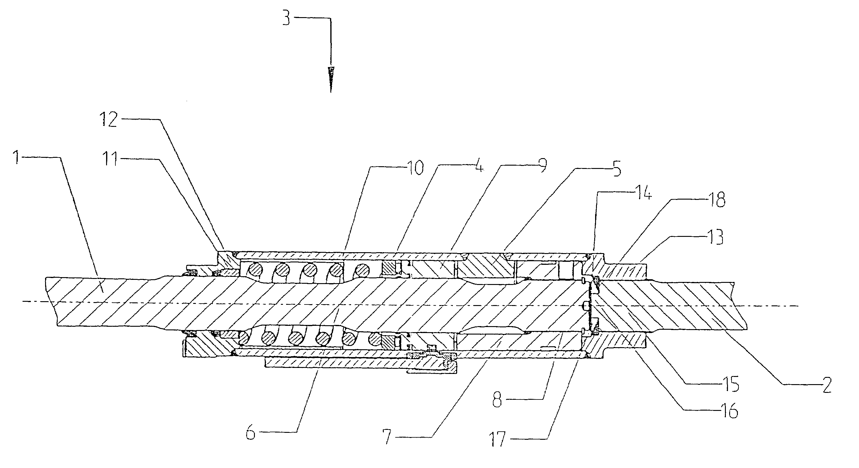
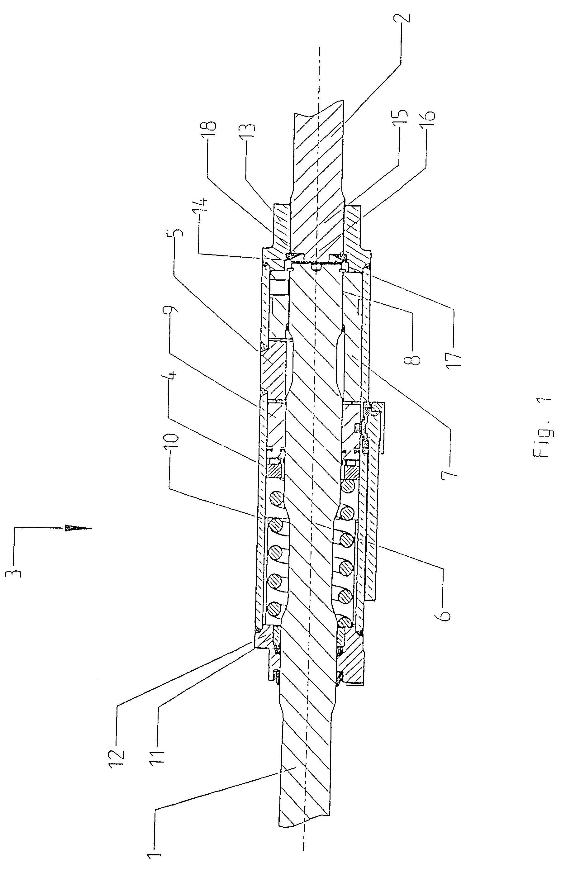
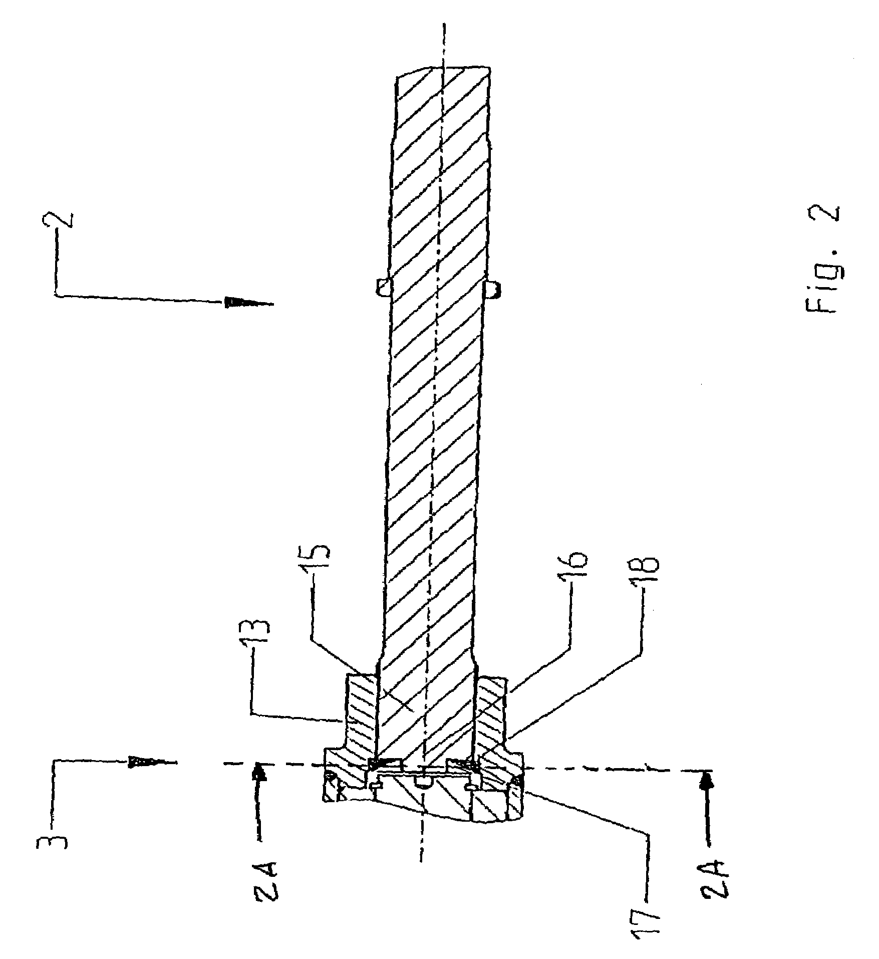
[0026]Referring to the drawings in particular, the two FIGS. 1 and 2 show a split stabilizer comprising a first stabilizer part 1 and a second stabilizer part 2, the two being connected to one another via a clutch generally designated 3. The clutch 3 comprises an outer rotary part 4 in the form of a cylindrical housing with a rotary wing 5, which is rotating in unison and is directed inwardly, and with an inner rotary part 6 with an outwardly directed rotary wing 7. The inner rotary part 6 and its outwardly directed rotary wing 7 are connected to one another, rotating in unison, by means of teeth 8. Both rotary wings 5 and 7 are located on a common radial plane and form between them two opposite coupling spaces. A coupling sleeve 9 is guided on the inner rotary part 6 with two conical coupling claws in an axially displaceable manner, the coupling claws engaging the two free coupling spaces of the rotary wings 5 and 7. The coupling sleeve 9 is acted on by the force of a compression s...


PUM

PropertyMeasurementUnit
temperatureaaaaaaaaaa
pressureaaaaaaaaaa
areaaaaaaaaaaa

Abstract

A connection of the stabilizer parts of a two-part stabilizer to an actuator is usually performed in a positive-locking manner, as a result of which an additional axial securing and hydraulic sealing toward the outside become necessary. To simplify the design and the manufacturing process, it is provided that the teeth between the outer rotary part (4) and the second stabilizer part (2) be made clearance-free and welded together by a circumferential weld seam (18), wherein the seam area is preheated to a temperature of 350° C. and subsequently cooled to a martensite content of 30% in the microstructure.

Description

CROSS REFERENCE TO RELATED APPLICATION[0001]This is a continuation of and claims the benefit (35 U.S.C. §120 and 365(c)) of copending International Application PCT / DE 03 / 01804 of Jun. 2, 2003, which designated inter alia the United States and which claims the priority of German Application DE 102 25 035.9 of Jun. 6, 2002. The entire contents of each application is hereby incorporated by reference in its entirety.FIELD OF THE INVENTION[0002]The present invention pertains to a split stabilizer with a first stabilizer part and a second stabilizer part, the two being connected to one another by an actuator having an inner rotary part with at least one outwardly directed rotary wing and to a corresponding manufacturing process for establishing a toothed connection of the outer rotary part of an actuator with the second stabilizer part, wherein the rotary part is a case-hardened steel and the stabilizer part is a spring steel.BACKGROUND OF THE INVENTION[0003]Such stabilizers are used espe...

Claims


Application Information

Patent Timeline
Patent Type & Authority Patents(United States)
IPC IPC(8): B60G21/055B23K9/00
CPCB60G21/0553B60G2202/135B60G2206/427B60G2206/8201F16D1/068B60G21/055
Inventor REICHEL, KLAUSBAUSTIAN, TORSTENKRUGER, WINFRIEDBEETZ, STEFANKLASEN, CHRISTIANPETERS, JOCHEN
Owner ZF FRIEDRICHSHAFEN AG
Why Eureka
Try Eureka