Method of operating a resonant power converter and a controller therefor

a technology of resonant power converter and controller, which is applied in the direction of electric variable regulation, process and machine control, instruments, etc., to achieve the effect of reducing or eliminating the requirement for discrete steps in power and improving the control of the switching period

Active Publication Date: 2012-12-25
NXP BV
View PDF25 Cites 34 Cited by
  • Summary
  • Abstract
  • Description
  • Claims
  • Application Information

AI Technical Summary

Benefits of technology

[0009]It is an object of the present invention to allow improved control of the switching period, and thus to reduce or eliminate the requirement for discrete steps in power.
[0012]Preferably, there is a delay between opening the first switch and closing the second switch such that zero voltage switching of the second switch occurs. Further, there may be a second delay between opening the second switch and closing the first switch such that zero voltage switching of the first switch occurs. This is known to reduce switching losses in the switches.
[0021]The controller preferably may comprise a respective drive circuit for driving each of the first and the second switches. More preferably the controller including the respective drive circuits is packaged in a single package, and more preferably still, the controller including the respective drive circuits is implemented on a single semiconductor chip. This provides a particularly convenient and space-efficient solution.

Problems solved by technology

Further, there may be a second delay between opening the second switch and closing the first switch such that zero voltage switching of the first switch occurs.

Method used


Image

  • Method of operating a resonant power converter and a controller therefor
  • Method of operating a resonant power converter and a controller therefor
  • Method of operating a resonant power converter and a controller therefor

Examples


Embodiment Construction

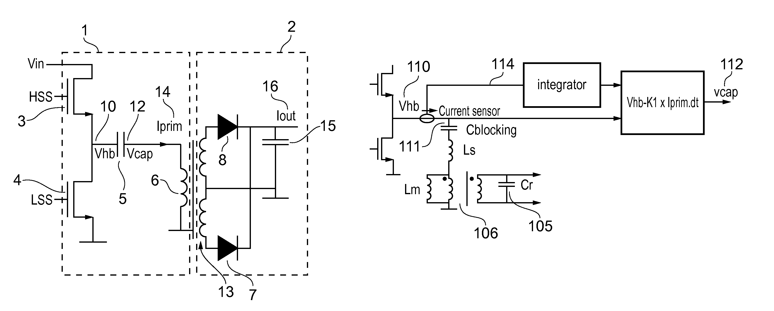
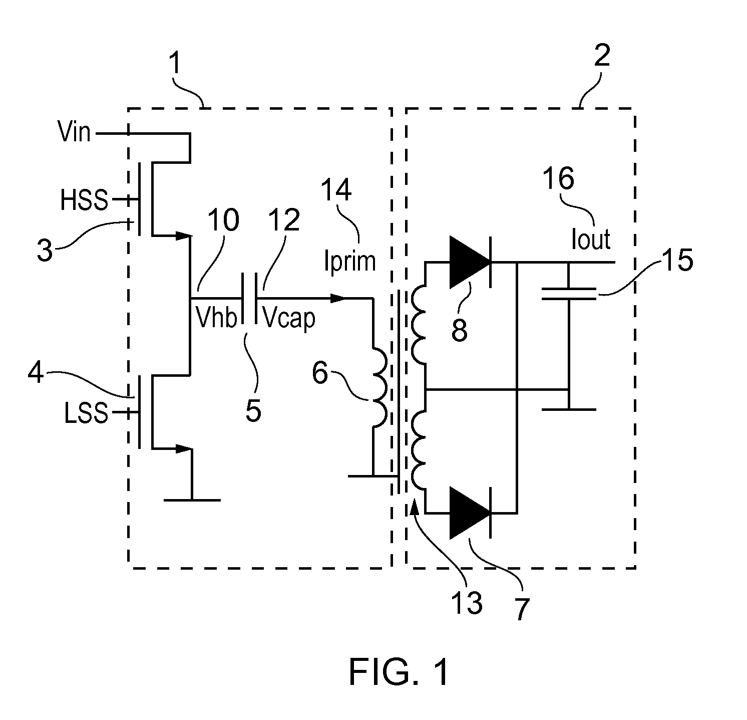
[0037]FIG. 1 shows a resonant power supply for use in accordance with embodiments of the invention. The resonant power supply comprises a primary side circuit 1, and a secondary side circuit 2. The primary side circuit 1 comprises a pair of switches 3 and 4, that is a HSS 3 in series with a LSS 4. In use the switches are connected in series between ground and a supply voltage, Vin. The node 10 between the switches is termed the half bridge node, and the voltage at this point is Vhb. The half bridge node 10 is series connected to the primary winding 6 of a transformer 13 via resonant capacitor Cr, 5. The voltage at the capacitor terminal 12 on the transformer side is depicted by Vcap. The current 14 in the primary circuit is Iprim. The inductance in the primary side circuit, and in particular in the primary winding 6, comprises two components, that is the magnetising inductance (Lm) and the series inductance (Ls). Thus together with the resonant capacitance Cr 5 the primary side circ...


PUM


Abstract

A method of operating a resonant power converter(1, 2), having a high side switch(3) and a low side switch(4), is disclosed in which the switching is controlled to allow for improved operation at low power levels. The method involved an interruption to the part of the switching cycle in which the low side switch (4) is normally closed, by opening the switch at a particular moment in the cycle which allows the energy to be store in the resonance capacitor (5). Since, as a result, the energy is largely not resonating but stored in a single component, the time quantization of the mode of operation is significantly reduced or eliminated.

Description

FIELD OF THE INVENTION[0001]The present invention relates to power supplies and in particular to resonant mode power converters.[0002]The present invention is particularly relevant to devices that require a variable level of power, and to devices that require a normal level of power as well as a lower level of power for use in a standby mode. Examples of such devices are consumer electronics such as computers, televisions and the like.BACKGROUND OF THE INVENTION[0003]Power converters for consumer applications typically operate at partial load under standby conditions for a relatively large part of their lifetime. Whilst functioning in this mode, it is desirable to draw power from the mains supply at as low level as is conveniently possible. Therefore it is desirable to use a power converter design for the power supply which operates with a high efficiency not only under full load conditions, but also for partial load, and particularly for low power standby mode.[0004]Power supplies ...

Claims


Application Information

Patent Timeline
Patent Type & Authority Patents(United States)
IPC IPC(8): H02M3/335H02M7/00
CPCH02M3/3376H02M2001/0032Y02B70/1433Y02B70/16Y02B70/10H02M1/0032
Inventor HALBERSTADT, HANS
Owner NXP BV
Why Eureka
Try Eureka