Method of estimating an angle of attack and an angle of sideslip of an aircraft

a technology of aircraft angle and angle of attack, which is applied in the direction of vehicle position/course/altitude control, process and machine control, instruments, etc., can solve the problems of increasing the overall cost of aircraft, difficult to detect failure, and not being suitable for military aircraft us

Inactive Publication Date: 2012-12-25
ALENIA AERONAUTICA SPA
View PDF16 Cites 7 Cited by
  • Summary
  • Abstract
  • Description
  • Claims
  • Application Information

AI Technical Summary

Problems solved by technology

In sensors based on “Pitot tubes” any overheating or obstruction of the sensor is detected by control signals; in “fin”-type sensors, however, it is much more difficult to detect failure since, for example, if a “fin” is deformed or inclined there are no measurement or feedback systems that can detect the deformation or displacement.
This leads to an increase in the overall costs of the aircraft 2.
Moreover, because of the large number of sensors and the fact that they are arranged projecting from the surface of the aircraft 2, they are easily visible by detection radar and are not therefore suitable for use on military aircrafts.

Method used


Image

  • Method of estimating an angle of attack and an angle of sideslip of an aircraft
  • Method of estimating an angle of attack and an angle of sideslip of an aircraft
  • Method of estimating an angle of attack and an angle of sideslip of an aircraft

Examples


Embodiment Construction

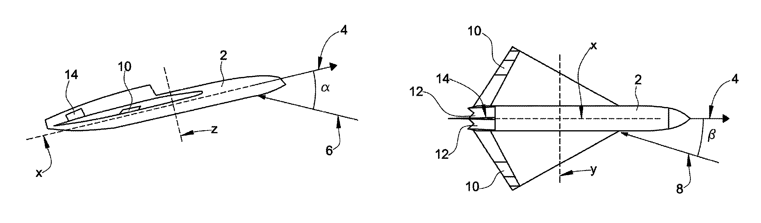
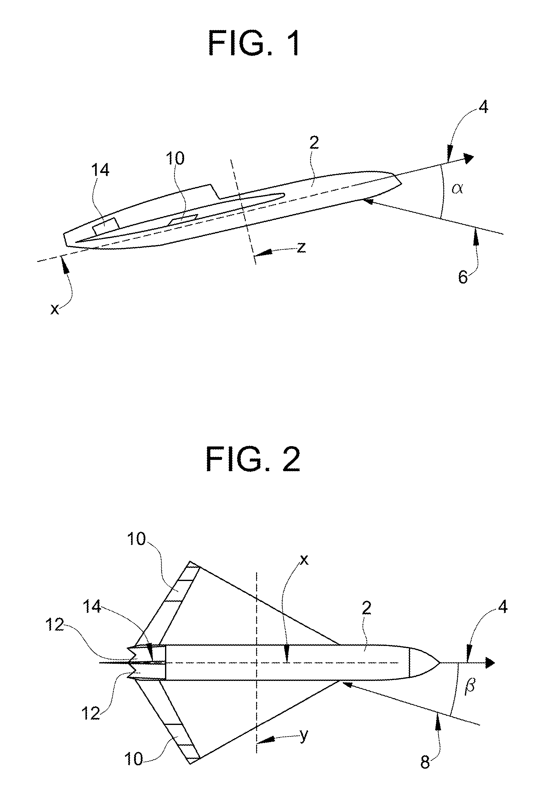
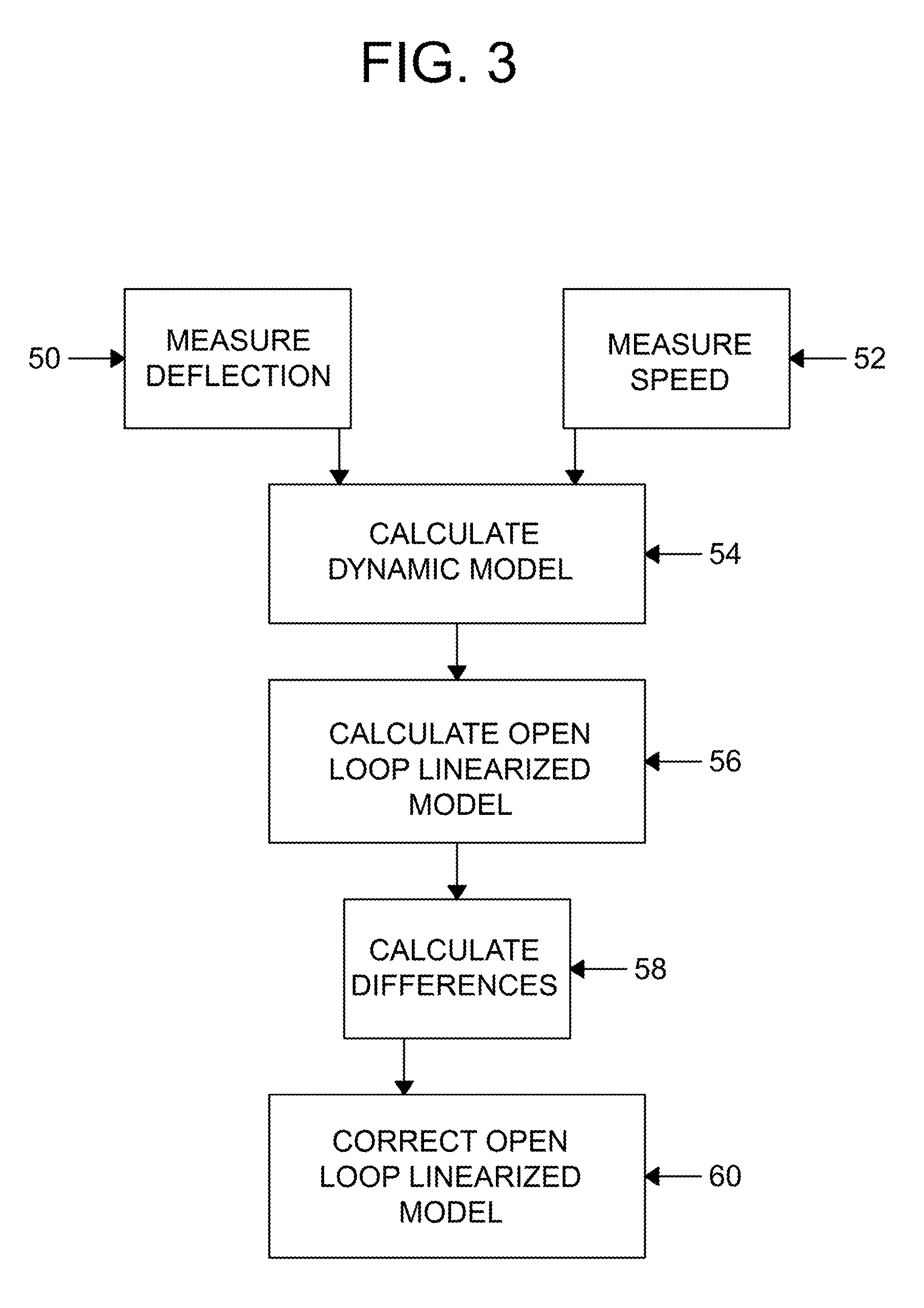
[0019]Briefly, the method consists of calculating a model of the aircraft 2 supplied with measured flight commands, the model being used to perform an open-loop estimate of the state of the system.

[0020]However, the performance of an open-loop state estimator or observer is not adequate to obtain reliable data because of disturbances, parametric uncertainties, and non-modeled variables such as wind-speed.

[0021]The open-loop estimator is therefore corrected by inserting a control loop, in particular a numeric control filter which ensures the convergence of the variables of the model with real values measured by sensors of the aircraft 2, rejecting external disturbances.

[0022]The convergence of the values of the model variables with values measured on board the aircraft 2 is ensured since the control filter is designed so as to render the system globally stable.

[0023]The equations of the open-loop state observer are therefore corrected, by means of the control loop, by a quantity whic...


PUM


Abstract

A method for estimating an angle of attack and an angle of sideslip of an aircraft having a plurality of control surfaces each adjustable with respect to an associated reference surface. The method includes measuring quantities representative of the angle formed by each control surface with respect to the associated reference surface, and measuring an effective rolling speed, an effective pitching speed, and an effective yawing speed of the aircraft. A linearized model of a state observer is defined according to the following equations:{ x.=Ax+Bu+L⁢⁢δ⁢⁢yy=Cx+Du⁢wherein u is a vector containing the values of the quantities of each control surface, x is a vector including an estimated angle of attack, an estimated angle of sideslip, an estimated rolling speed, an estimated pitching speed and an estimated yawing speed, δy is an error vector including the errors between the measured speeds and the respective estimated speeds, y is a measure vector including the values of the measured speeds, A,B,C,D are matrices representative of the behavior of the aircraft in unperturbed motion and L is a feedback matrix including the gains of a predetermined numeric control filter. The estimated angle of attack and the estimated angle of sideslip are obtained from the model to use as an actual angle of attack and an actual angle of sideslip of the aircraft.

Description

[0001]This application claims benefit of Serial No. TO2008A000923, filed 11 Dec. 2008 in Italy and which application is incorporated herein by reference. To the extent appropriate, a claim of priority is made to the above disclosed application.BACKGROUND[0002]The present invention relates to a method of estimating the angle of attack and the angle of sideslip of an aircraft.[0003]More specifically, the invention relates to a method of estimating the angle of incidence or attack and the angle of sideslip of an aircraft.[0004]The angle of incidence or attack and the angle of sideslip are two quantities which define parameters of the motion of an aircraft which must be monitored and controlled constantly to ensure the safety of the aircraft.[0005]FIG. 1 shows a section through an aircraft 2 which is travelling along a direction of movement represented by a first vector 4. A second vector 6 represents the direction of an airflow which strikes the aircraft 2 longitudinally and α is the a...

Claims


Application Information

Patent Timeline
Patent Type & Authority Patents(United States)
IPC IPC(8): G05D1/08G06F17/16
CPCG01P13/025G05D1/0825
Inventor CHIESA, ALBERTO
Owner ALENIA AERONAUTICA SPA
Why Eureka
Try Eureka