Automated Motor Control

a technology of automatic motor control and motor control, which is applied in the direction of motor/generator/converter stopper, dynamo-electric converter control, dynamo-electric gear control, etc., can solve the problems of reducing the robustness and disturbance rejection properties of the controller, time-consuming and laborious manual tuning of the controller, and often insufficient control system expertise, so as to reduce the total number of controllers

Active Publication Date: 2014-09-18
TEXAS INSTR INC
View PDF6 Cites 38 Cited by
  • Summary
  • Abstract
  • Description
  • Claims
  • Application Information

AI Technical Summary

Benefits of technology

[0007]Generally speaking and pursuant to these various embodiments, input-output linearization (IOL) and extended state observer (ESO) techniques are applied to Field Oriented Control (FOC) for Permanent Magnet Synchronous Motors (PMSM). In one such approach, at least one gain value is determined based at least in part on a given bandwidth value. Operating parameters for the motor are determined based on the at least one gain value and information from a current sensor regarding motor current. Control signals used to control the motor are determined based on the determined operating parameters. Accordingly, automated control can be effected through setting a bandwidth value through the implementation of IOL and ESO techniques. Moreover, as compared to previous applications, the total number of controllers can be reduced. These and other benefits may become clear upon making a thorough review and study of the following detailed description.

Problems solved by technology

Performance is usually measured in terms of the controller's disturbance rejection properties, its robustness against parameter uncertainty, and settling times. However, tuning controllers manually can be time consuming and tedious given a large application space such as motor control because motors are applied in a wide variety of applications having different motor control needs.
Changing applications often degrades robustness and disturbance rejection properties of the controller.
Also, many applications require control systems expertise that is often not available to software engineers that develop microcontroller based motor control solutions.
Also, there is no closed form solution to specify desired controller bandwidth (the amount of computation capability for a controller when controlling a motor) while using this approach.
Unnecessarily increasing the number of controllers not only increases complexity in gain design but also degrades system performance.

Method used


Image

  • Automated Motor Control
  • Automated Motor Control
  • Automated Motor Control

Examples


Embodiment Construction

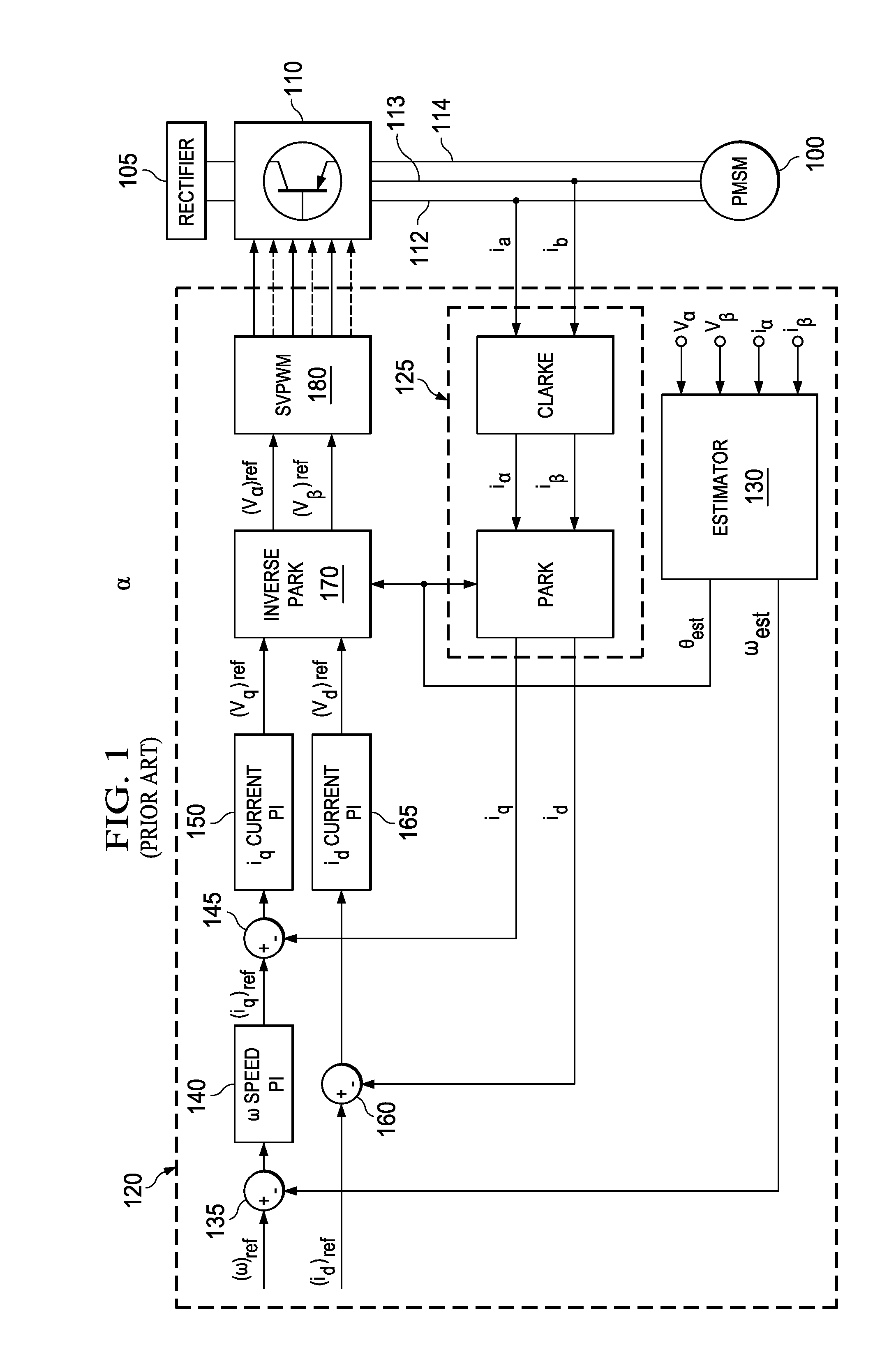
[0017]Referring now to the drawings, and in particular to FIG. 1, a prior approach to motor control will be described to help illustrate the advances described herein. In FIG. 1, a PMSM 100 is controlled using a traditional PI-based field oriented control approach. A rectifier 105 provides power to an inverter 110. The inverter 110 includes various gates or switches to take power from the rectifier 105 and apply power to current paths 112, 113, 114 for the three windings of the motor 100. The inverter 110 is controlled by the receipt of control signals from a control device 120. Current for the motor 100 is sensed (ia and ib) and transformed using the known mathematical transform, Clarke-Park transformation 125, to obtain feedback values iq and id. An estimator 130 takes available motor current (iα and iβ) and applied voltage (Vα and Vβ) values and outputs estimated rotor position θest and speed ωest. The estimated rotor position θest is used in the Park transformations. The estimat...


PUM


Abstract

Input-output linearization (IOL) and extended state observer (ESO) techniques are applied to a Field Oriented Control (FOC) for Permanent Magnet Synchronous Motors (PMSM). In one such approach, at least one gain value is determined based at least in part on a given bandwidth value. Operating parameters for the motor are determined based on the at least one gain value and information from a current sensor regarding motor current. Control signals used to the control the motor are determined based on the determined operating parameters. Accordingly, automated control can be effected through setting a bandwidth value through the implementation of IOL and ESO techniques.

Description

TECHNICAL FIELD[0001]This invention relates generally to electric motor controllers, and more specifically to controlling electric motors with an improved automation aspect.BACKGROUND[0002]Electric motors of various kinds are well known. Generally speaking, electric motors are driven by applying a current to inputs of the motor, which currents create a magnetic field that interacts with another magnetic field to turn the motor's rotor. For example, one or more permanent magnets can provide magnetic fields to interact with the magnetic fields produced by the input current. The motor's turning can be controlled by controlling various aspects of the current applied to the motor.[0003]Motors come in a variety of designs. A common design includes having three windings of wires through which current flows, which current flow creates magnetic fields that interact with a plurality of permanent magnets. To control a motor with a complicated design, the current control may need a complicated ...

Claims


Application Information

Patent Timeline
Patent Type & Authority Applications(United States)
IPC IPC(8): H02P21/00
CPCH02P21/0003H02P21/13H02P6/28
Inventor KATARIYA, ASHISH S.MAGEE, DAVID P.
Owner TEXAS INSTR INC
Why Eureka
Try Eureka