Plasma processing apparatus and method of plasma distribution correction

a technology of plasma distribution and processing apparatus, which is applied in the direction of instruments, fluid pressure measurement, coatings, etc., can solve the problems of complicated configuration of the apparatus, and achieve the effect of simplifying the apparatus configuration

Active Publication Date: 2013-01-01
TOKYO ELECTRON LTD
View PDF15 Cites 73 Cited by
  • Summary
  • Abstract
  • Description
  • Claims
  • Application Information

AI Technical Summary

Benefits of technology

[0009]The present invention provides a plasma processing apparatus and a method of plasma distribution correction whereby a sheath can be prevented from becoming distorted, the configuration of the apparatus can be simplified, and particles can be prevented from attaching to a substrate.

Problems solved by technology

However, the above-described apparatus requires a drive unit having a shaft and a motor in order to mechanically raise the focus ring, thus giving rise to the problem that the configuration thereof becomes complicated.
The apparatus has another problem that when the focus ring moves, deposits adhering thereto separate on impact of the movement and fly apart in particles, thus attaching to a wafer.

Method used


Image

  • Plasma processing apparatus and method of plasma distribution correction
  • Plasma processing apparatus and method of plasma distribution correction
  • Plasma processing apparatus and method of plasma distribution correction

Examples


first embodiment

[0049]First, an explanation will be made of a plasma processing apparatus in accordance with the present invention.

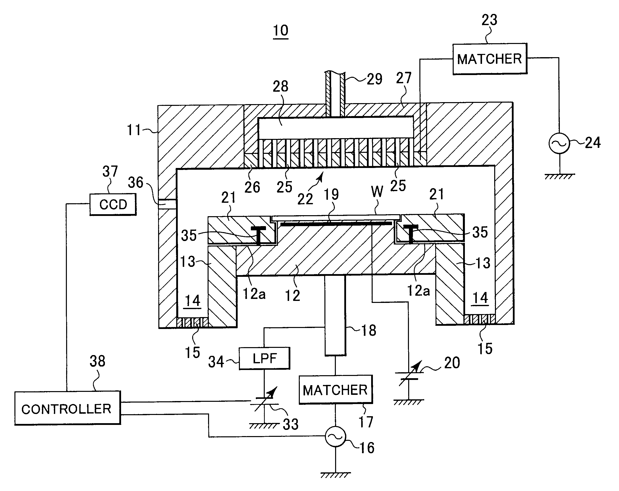
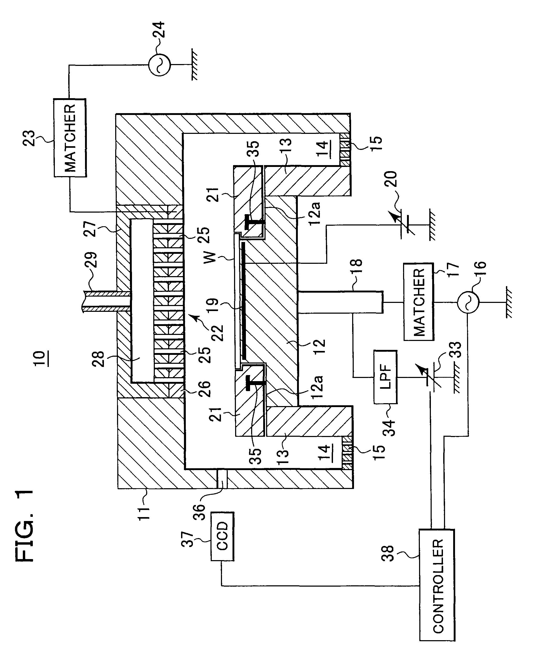
[0050]FIG. 1 is a cross-sectional view schematically illustrating the configuration of a plasma processing apparatus in accordance with a first embodiment of the present invention. This plasma processing apparatus is configured to perform an etching processing on a semiconductor wafer serving as a substrate.

[0051]In FIG. 1, a plasma processing apparatus 10 is provided with a chamber 11 (housing chamber) for housing semiconductor wafers (hereinafter simply referred to as “wafers”) W having a diameter of, for example, 300 mm, and an electrostatic chuck 12 (mounting stage) to be mounted with a wafer W is disposed within the chamber 11. The electrostatic chuck 12 is formed of a lower disc-shaped member having a specific diameter on which there is placed an upper disc-shaped member having a diameter smaller than the diameter of the lower disc-shaped member. Note that the ele...

second embodiment

[0084]Next, an explanation will be made of a plasma processing apparatus in accordance with the present invention.

[0085]The present embodiment is basically the same in configuration and effect as the above-described first embodiment and only differs in the way the amount of wear in a focus ring is measured. The same parts of configuration and effect, therefore, will not be explained further and only the different parts thereof will be explained hereinafter.

[0086]FIG. 6 is a cross-sectional view schematically illustrating the configuration of a plasma processing apparatus in accordance with the present embodiment.

[0087]In FIG. 6, a plasma processing apparatus 40 is provided with a focus ring wear measurement unit 41. The focus ring wear measurement unit 41 is provided with a laser light oscillator 42 for irradiating infrared low-coherent light as laser light (for example, SLD having a wavelength of 1300 nm), a 2×2 coupler 44 connected through the laser light oscillator 42 and an opti...

third embodiment

[0104]Next, an explanation will be made of a plasma processing apparatus in accordance with the present invention.

[0105]The present embodiment is basically the same in configuration and effect as the above-described first embodiment and only differs in the way the amount of wear in a focus ring is predicted. The same parts of configuration and effect, therefore, will not be explained further and only the different parts thereof will be explained hereinafter.

[0106]FIG. 8 is a cross-sectional view schematically illustrating the configuration of a plasma processing apparatus in accordance with the present embodiment.

[0107]In FIG. 8, a plasma processing apparatus 50 is provided with a sensor 51 provided on the side wall of a chamber 11 and a controller 52 (control unit) connected to the sensor 51. The sensor 51 measures a pressure and a temperature (plasma processing conditions) within the chamber 11 and transmits the result of measurement to the controller 52.

[0108]The controller 52 is...


PUM

PropertyMeasurementUnit
diameteraaaaaaaaaa
DC voltageaaaaaaaaaa

Abstract

A plasma processing apparatus can prevent a sheath from becoming distorted, simplify a configuration of the apparatus, and prevent particles from attaching to a substrate. The plasma processing apparatus performs plasma processing on the substrate. A housing chamber houses the substrate. A mounting stage is disposed within the housing chamber and mounted with the substrate. An annular member is disposed in the mounting stage. A power supply unit supplies high-frequency power to the mounting stage. An observation unit optically observes the distribution of the plasma. A voltage applying unit applies a DC voltage to the annular member. A control unit sets the value of the DC voltage to be applied based on the observed plasma distribution.

Description

BACKGROUND OF THE INVENTION[0001]1. Field of the Invention[0002]The present invention relates to a plasma processing apparatus and a method of plasma distribution correction and, more particularly, to a plasma processing apparatus having a focus ring.[0003]2. Description of the Related Art[0004]A plasma processing apparatus for performing a plasma processing on a wafer serving as a substrate using plasma is provided with a housing chamber (chamber) for housing wafers, a mounting stage disposed within the chamber to be mounted with a wafer, and a focus ring disposed on the mounting stage so as to surround the wafer. The focus ring is made of silicon and converges ions in plasma within the chamber onto the wafer, in order to improve the efficiency of a plasma processing, for example, an etching processing, to be performed on the wafer.[0005]In addition, as shown in FIG. 11A, a focus ring 110 maintains a potential difference between the focus ring 110 and plasma 111 the same as a poten...

Claims


Application Information

Patent Timeline
Patent Type & Authority Patents(United States)
IPC IPC(8): H01L21/00C23C16/00
CPCH01J37/32091H01J37/32706
Inventor TANAKA, SATOSHIKOSHIMIZU, CHISHIOIWATA, MANABUMATSUMOTO, NAOKIITO, TORU
Owner TOKYO ELECTRON LTD
Why Eureka
Try Eureka