Oil combatting vessel

a technology of oil combating vessel and oil tank, which is applied in special-purpose vessels, water cleaning, separation processes, etc., can solve the problems of difficult collection of spilled oil from among the ice in such circumstances, environmental damage, and oil damage, and achieve the effect of minimizing the height variation of the oil collecting device caused by sea swell

Active Publication Date: 2013-01-01
AKER ARCTIC TECH
View PDF20 Cites 12 Cited by
  • Summary
  • Abstract
  • Description
  • Claims
  • Application Information

AI Technical Summary

Benefits of technology

[0011]The density of the oil or oil refining product to be collected is smaller than that of the water, so the oil, which has been separated from the ice blocks that were pushed down, tends to rise through the separating structure to the water surface. In an embodiment this phenomenon is used to reduce the water content of the oil / water mixture, which is processed with the oil collecting device. Reducing the water content of the mixture facilitates the separation of oil from the water. The oil / water mixture can also be transferred almost as such to the container in the vessel, whereby a reduction in the water content of the mixture reduces the volume of the necessary container.
[0013]In one embodiment the separating structure, which is installed between the hulls, can be long in relation to the length of the side hull. By using a long separating structure, the oil collecting efficiency and / or oil collecting performance can be increased.
[0017]According to an embodiment the vessel is a three-hulled vessel designed especially for ice breaking, whereby the separating structures are situated in shelter between the middle hull and side hulls of the vessel. The vessel can be arranged so that it breaks mainly only quite large ice blocks from the fast ice, which ice blocks do not substantially get through the grate in the separating structure. In many situations an adequate collecting efficiency can be obtained by pushing said large ice blocks underneath the water surface with the aid of the immobile or passively vibrating separating structure. The immobile or passively vibrating separating structure breaks off from the large ice blocks an as small amount as possible of small blocks and / or ice sludge, which, when they have risen through the separating structure to the water surface, could make the collecting of oil more difficult.
[0018]According to an embodiment the vessel is used to collect oil under circumstances, where the ice is already in blocks. Also thereby an advantage is obtained by the fact that the vessel has many hulls, even though the vessel does not necessarily need to be optimized for breaking ice. The separating structure can then be installed in a sheltered place between the hulls of the vessel, and height variations at the oil collecting device caused by swell of the sea can be minimized.

Problems solved by technology

Oil, which has been spilled from vessels or oil refineries, may cause environmental damages.
The oil damage may occur in an environment where a sea, lake or river is covered by an ice cover or ice blocks.
Collecting the spilled oil from among the ice in such circumstances is difficult.
Since the size of the vibrating screen is limited, the vibrating machinery must be able to move the heavy screen with such an amplitude and frequency, which significantly intensifies the separation of the oil from the ice blocks.
The vibration of the screen may form small ice blocks and ice sludge, which, when they have risen to the water surface through the screen, may make the collecting of oil more difficult.

Method used


Image

  • Oil combatting vessel
  • Oil combatting vessel
  • Oil combatting vessel

Examples


Embodiment Construction

[0040]The separating structure according to the invention is suited for use especially in a three-hulled vessel, i.e. a trimaran. It is preferable if the vessel is further able to break fast ice.

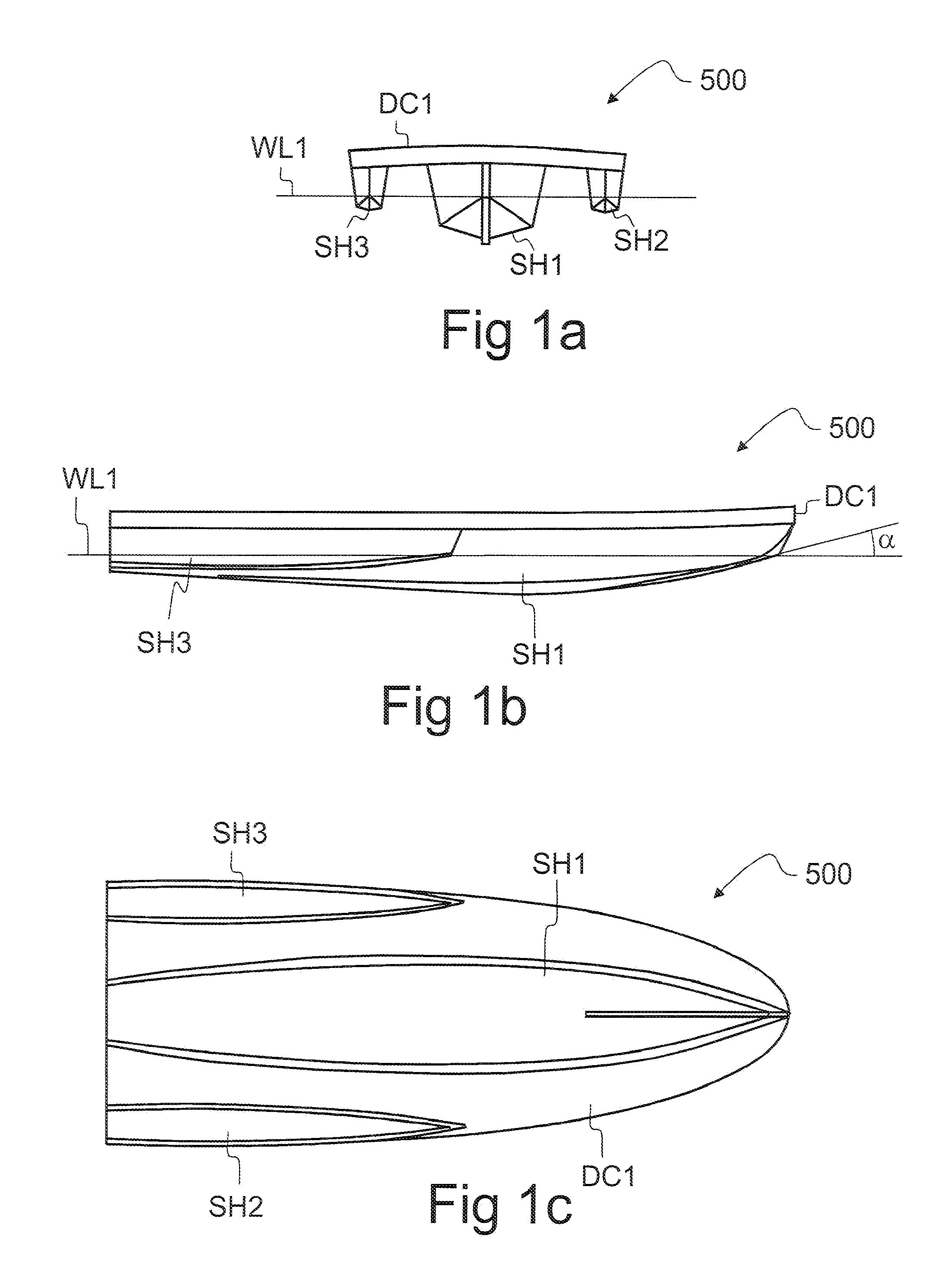
[0041]Referring to FIGS. 1a-1c, the three-hulled vessel 500 comprises a middle hull SH1, a right-side side hull SH3 and a left-side side hull SH2. The hulls SH1, SH2, SH3 can be connected to each other by the deck DC1. WL1 refers to the level of the water surface. The angle between the keel and the water surface is α. If there is no keel, the angle α means the angle between the bottom of the middle hull SH1 and the water surface at the height of the water surface WL1.

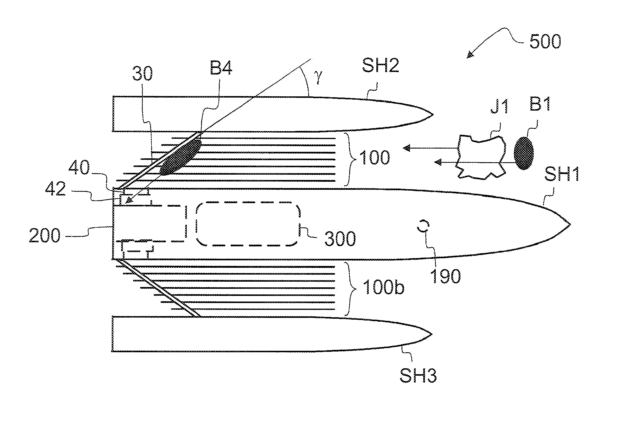
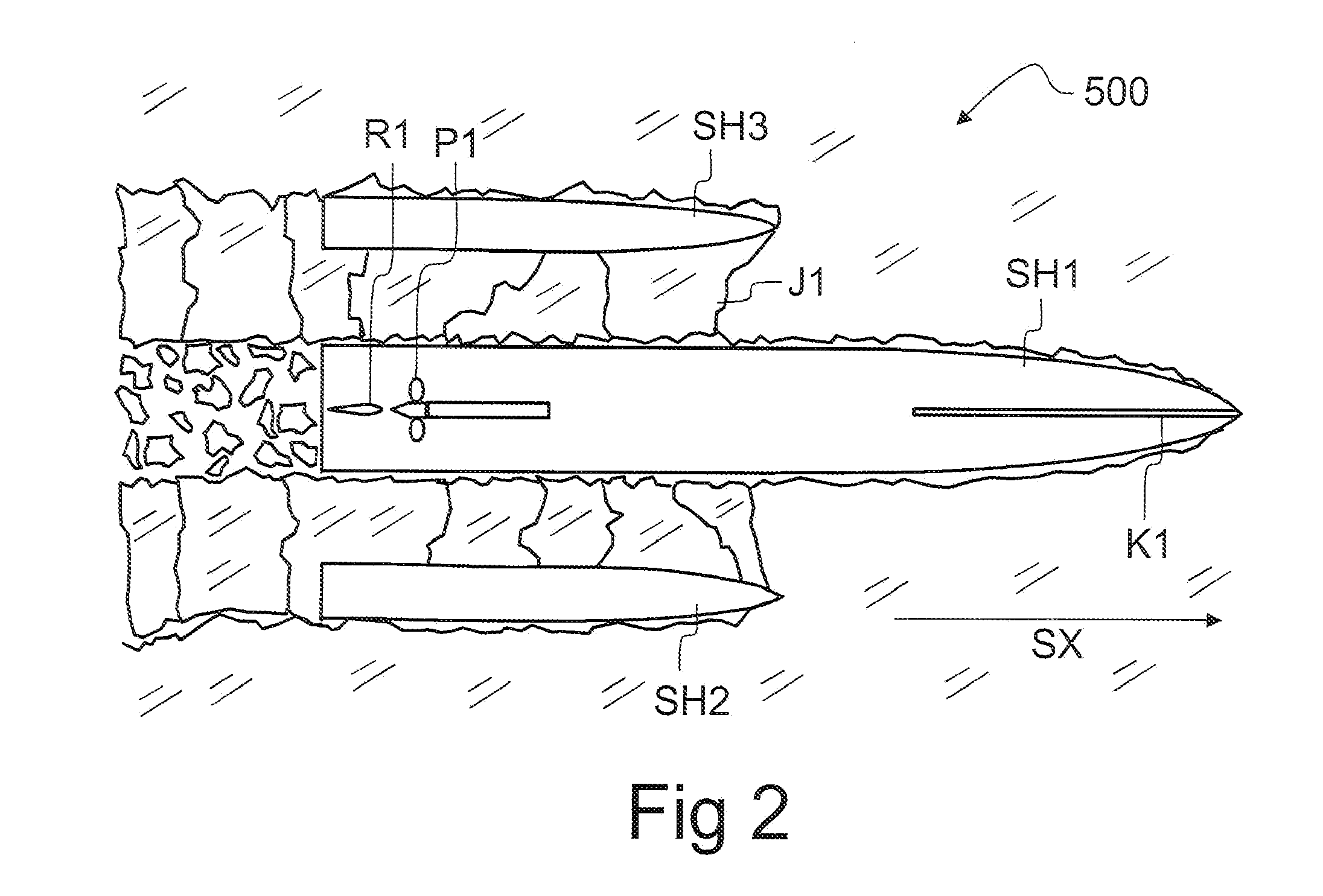
[0042]Referring to FIG. 2, the vessel 500 can be dimensioned to be suited especially for breaking fast ice. The prow of the side hulls SH2, SH3 can be situated essentially further back than the prow of the middle hull SH1, whereby the side hulls, which glide on top of the ice, can break blocks J1 from the ice on both sides of th...


PUM


Abstract

A three-hulled oil combatting vessel (500) has a separating structure (100), which pushes ice blocks (J1), which move between the middle hull (SH1) and side hulls (SH2, SH3) from the prow to the stern, underneath the water surface (WL1). The separating structure (100) may be a grate in the longitudinal direction of the vessel (500). The density of the oil (B4) or oil refining product to be collected is smaller than that of the water, so the oil (B3), which has been separated from the ice blocks (J1) that were pushed down, tends to rise through the separating structure (100) to the water surface. The separating structure (100) separates the oil (B3) from the ice blocks (J1) for easier collection into a container. The separated (B4) oil can thus be collected from the relatively ice-free water surface (WL1) with an oil collecting device (200), which may have a brush skimmer.

Description

CROSS REFERENCES TO RELATED APPLICATIONS[0001]This application is a U.S. national stage application of International App. No. PCT / FI2008 / 050619, filed Oct. 30, 2008, and claims priority on FI 20070827, filed Oct. 31, 2007; and FI 20085239, filed Mar. 19, 2008, the disclosures of all of which applications are incorporated by reference herein.STATEMENT AS TO RIGHTS TO INVENTIONS MADE UNDER FEDERALLY SPONSORED RESEARCH AND DEVELOPMENT[0002]Not applicable.BACKGROUND OF THE INVENTION[0003]The invention relates to an oil combatting vessel and a method for controlling oil damages with a vessel which has at least a middle hull, a first side hull, and a second side hull.[0004]Oil, which has been spilled from vessels or oil refineries, may cause environmental damages. The oil damage may occur in an environment where a sea, lake or river is covered by an ice cover or ice blocks. Collecting the spilled oil from among the ice in such circumstances is difficult.[0005]Publication EP1439119A1 prese...

Claims


Application Information

Patent Timeline
Patent Type & Authority Patents(United States)
IPC IPC(8): E02B15/04
CPCB63B35/32B63B35/08B63B2211/06Y02A20/204
Inventor IMMONEN, PAULI
Owner AKER ARCTIC TECH
Why Eureka
Try Eureka