
Method of forming an in-ear device

a technology of in-ear devices and ear plugs, which is applied in the direction of ear plugs, ear treatment, etc., can solve the problems of more irregular in-ear devices and uncertain bonding, and achieve the effects of mass production, reliable construction, and regular shape and appearan

Inactive Publication Date: 2013-01-01
HOWARD LIGHT IND LLC DELAWARE LLC
View PDF6 Cites 6 Cited by
  • Summary
  • Abstract
  • Description
  • Claims
  • Application Information

AI Technical Summary

Benefits of technology

The solution results in a more reliable, cost-effective, and uniformly shaped in-ear device with improved sound blocking and speaker pipe integration, reducing manufacturing costs and enhancing the device's quality and appearance.

Problems solved by technology

Adhesive applied to the tube tends to wipe off as the tube is inserted into the earplug passage, leaving an even more irregular in-ear device and with the bonding being uncertain.

Method used


Image

  • Method of forming an in-ear device
  • Method of forming an in-ear device
  • Method of forming an in-ear device

Examples


Embodiment Construction

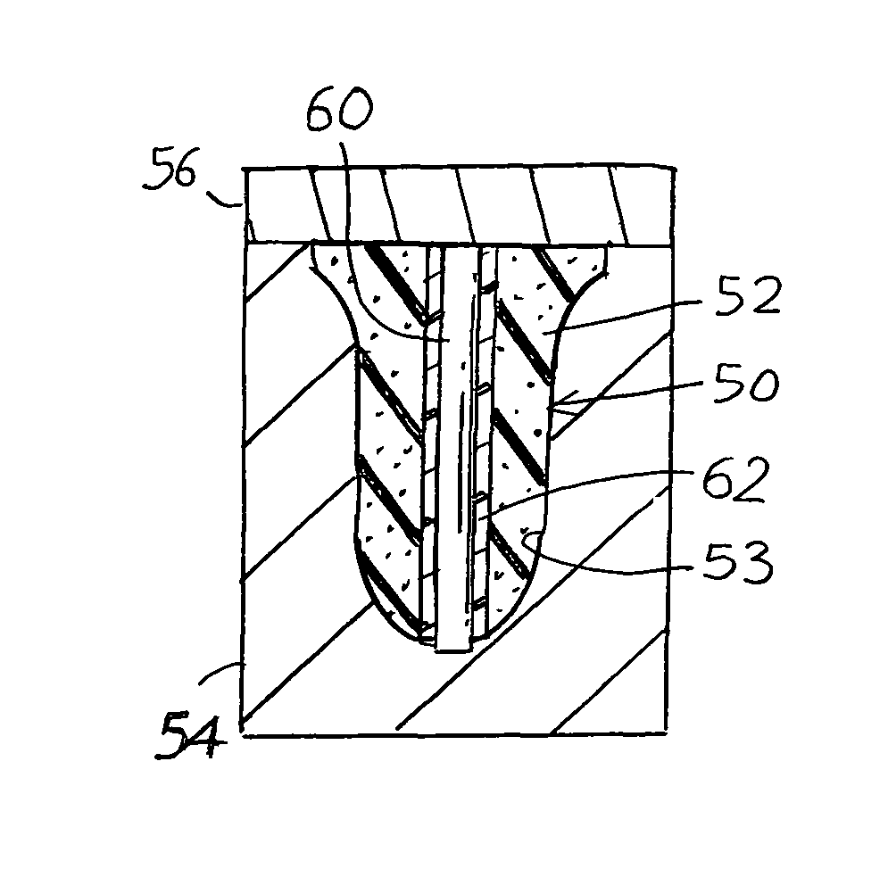
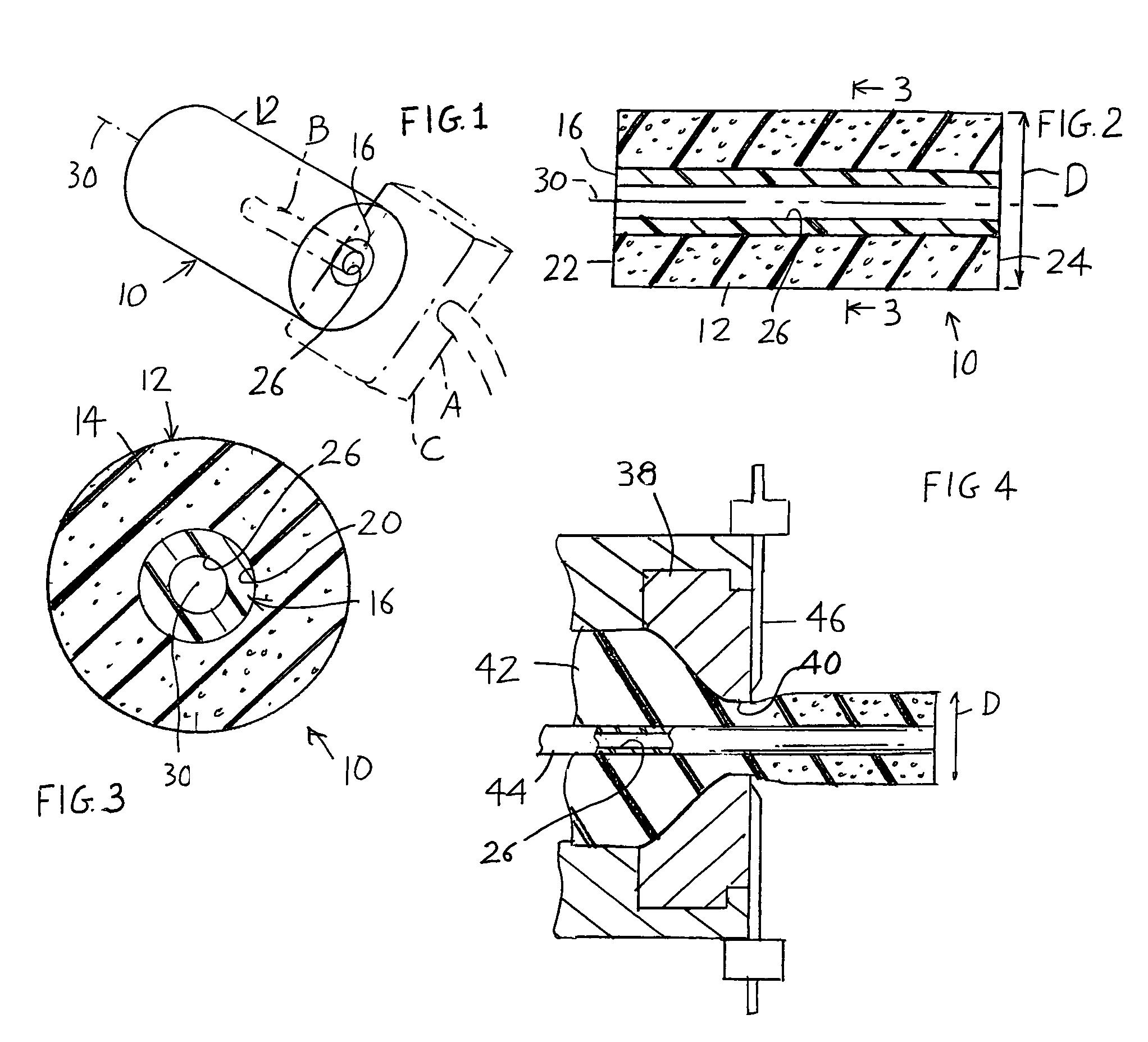
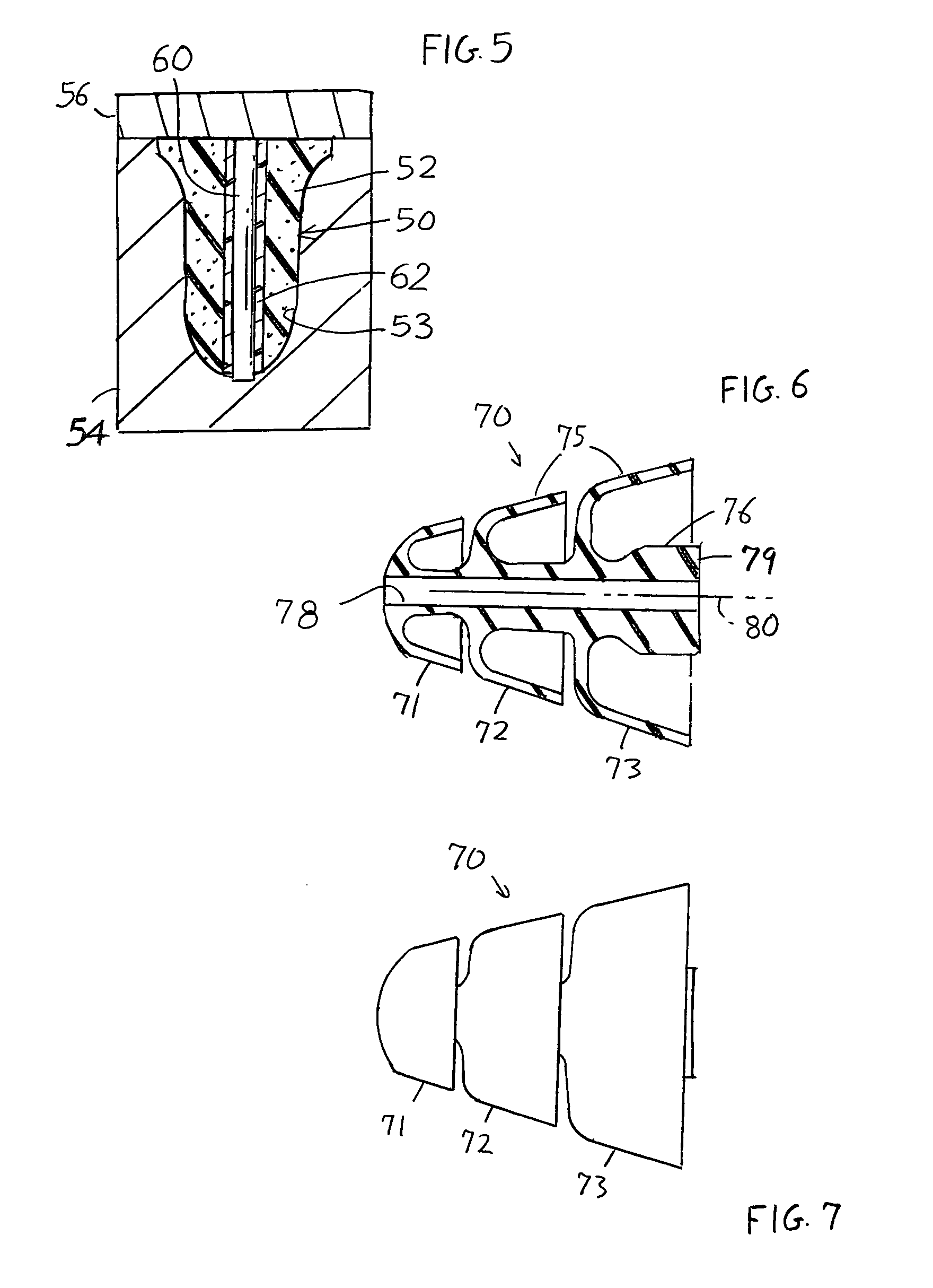
[0016]FIGS. 1-3 show an in-ear device 10 of the invention, which includes a body 12 of soft foam elastomeric polymer material 14 (an elastomeric material has a Young's Modulus of Elasticity of no more than 50,000 psi) and a tube 16 of stiffer elastomeric polymer material. The foam body has an outside diameter D of about 11 to 12 millimeters and is very soft, to seal to the walls of the person's ear canal. The tube 16 lies in a through body passage 20 of the body. The tube has an unobstructed (to sound) through tube passage 26 that extends along the length of the body between its front and rear ends 22, 24. The tube extends approximately parallel (within 100) to the earplug axis 30, and lies on the axis. Preferably the axes of the tube and body are coincident. The tube 16 is of material that is at least twice as stiff as the material of the body, which helps insertion of the device into an ear canal. In one example, the body material 14 is a resilient foam which has a Shore A number ...


PUM

PropertyMeasurementUnit
Young's Modulusaaaaaaaaaa
diameteraaaaaaaaaa
thicknessaaaaaaaaaa

Abstract

A method for forming a device (10) that fits into a person's ear canal, that carries sound from a pipe (B) of a speaker assembly (A) into the person's ear canal, and that blocks environmental noise. A first elastomeric material (14) is molded around an elongated core (16) to form a device body (12) with an outer surface that can seal to a person's ear canal. In one method, the first elastomeric material of the body is a soft foamable material and the core is a previously-formed tube (16) of a stiffer second elastomeric material, with the body bonded to the tube by being molded around it, either in a mold cavity or by extrusion through an extrusion head. In another method, the elastomeric material of the body is a non-foam, and the core (96) is a rigid pin that is removed from the earplug body after the earplug body has at least partially solidified.

Description

CROSS-REFERENCE[0001]Applicant claims priority from U.S. Provisional patent application Ser. No. 60 / 665,530 filed Mar. 25, 2005.BACKGROUND OF THE INVENTION[0002]There are situations in which environmental sound is to be blocked from a person's ear while controlled sound is delivered to the ear. One situation is a communication system for use in a noisy environment, and another is a hearing test. Instead of using ear cups or earmuffs with speakers in them, a speaker can be coupled to a through hole in a simple and low cost earplug. Such earplug can be of the type worn by workers in noisy environments such as factories, but with a passage to carry sound.[0003]One way to construct such an earplug with a passage in it, or in-ear device, is by modifying a foam elastomeric earplug of the type that is worn by workers in noisy environments such as factories to block sound. In such modification of an existing earplug, a hole is punched through the earplug to leave a passage that extends alon...

Claims


Application Information

Patent Timeline
Patent Type & Authority Patents(United States)
IPC IPC(8): B29C39/18
CPCA61F11/08
Inventor WOO, EDWINJENKINS, JR., JOHN A.
Owner HOWARD LIGHT IND LLC DELAWARE LLC
Learn More