
Floating support for oil production fitted with pack ice destruction devices, and an associated method

a technology of oil production and support, applied in waterborne vessels, special-purpose vessels, vehicles, etc., can solve the problems of difficult implementation, high cost of devices, and particularly disadvantageous behavior of hulls with vertical sides, and achieve the effects of limiting reaction, facilitating actuation, and effective striking

Inactive Publication Date: 2013-01-08
SAIPEM SA
View PDF9 Cites 17 Cited by
  • Summary
  • Abstract
  • Description
  • Claims
  • Application Information

AI Technical Summary

Benefits of technology

The present invention provides a floating support system for a ship that can effectively destroy pack ice on the sea surface using a pack ice destruction device. This device can be operated individually or in sequence, reducing unbalance of the ship's support. The destruction device is designed to be easy to actuate, effective in impact and bending, and limited in reaction unbalance. The system also includes means for guiding and moving the destruction tool in vertical translation and actuating downward and upward pivoting of the tool to reach a sufficient depth to pass through the entire thickness of the pack ice. This invention allows for efficient and safe operation of the ship in icy conditions.

Problems solved by technology

However a hull with vertical sides is particularly disadvantageous in terms of its behavior when faced with pack ice.
Such devices are extremely expensive to make and difficult to implement since they need to be operated at high levels of power and over the full thickness of the pack ice, and thus at the end of an arm that needs to be extremely rigid, and furthermore underwater for much of the time, since said pack ice presents a thickness that may be as much as several meters in certain locations.

Method used


Image

  • Floating support for oil production fitted with pack ice destruction devices, and an associated method
  • Floating support for oil production fitted with pack ice destruction devices, and an associated method
  • Floating support for oil production fitted with pack ice destruction devices, and an associated method

Examples


Embodiment Construction

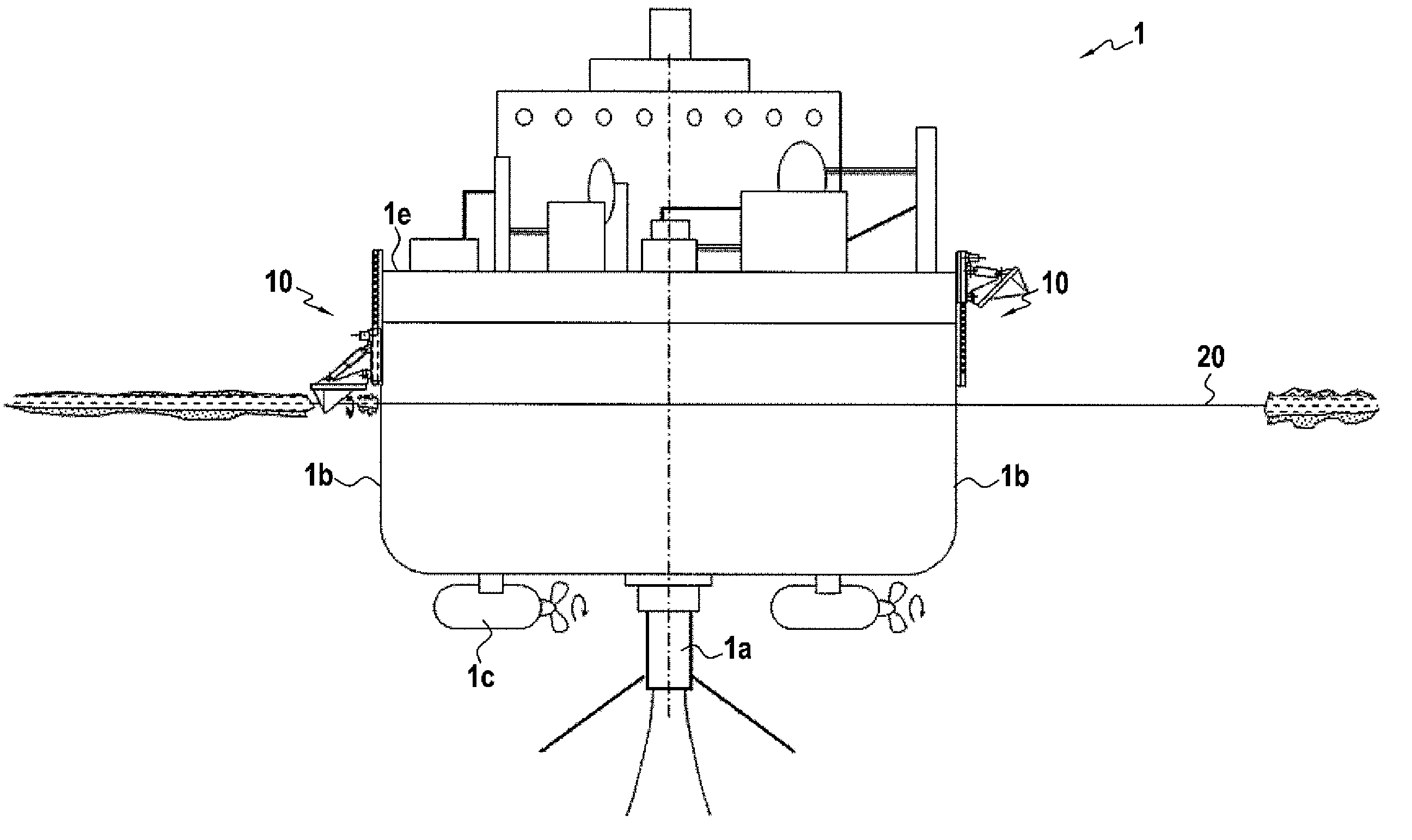
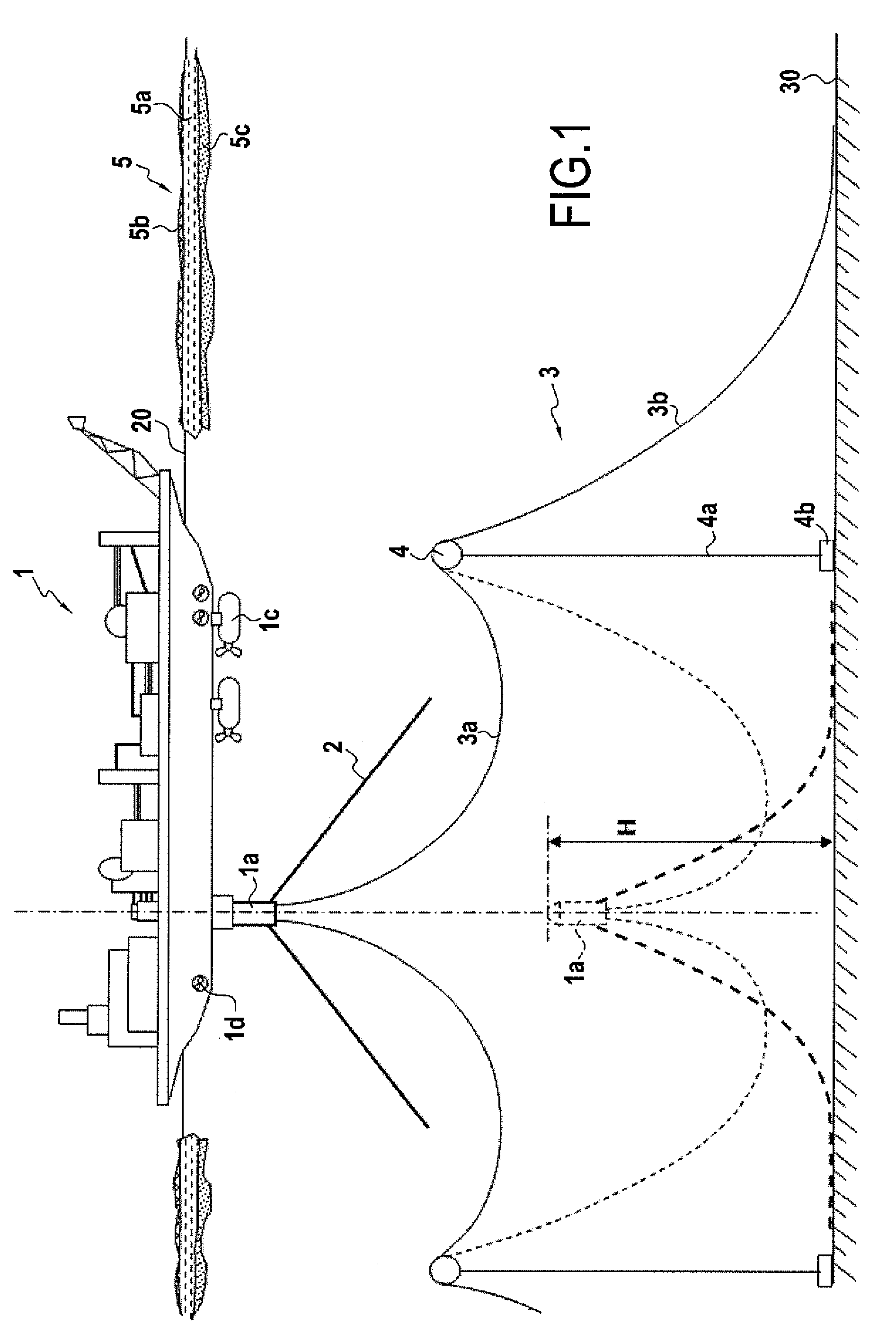
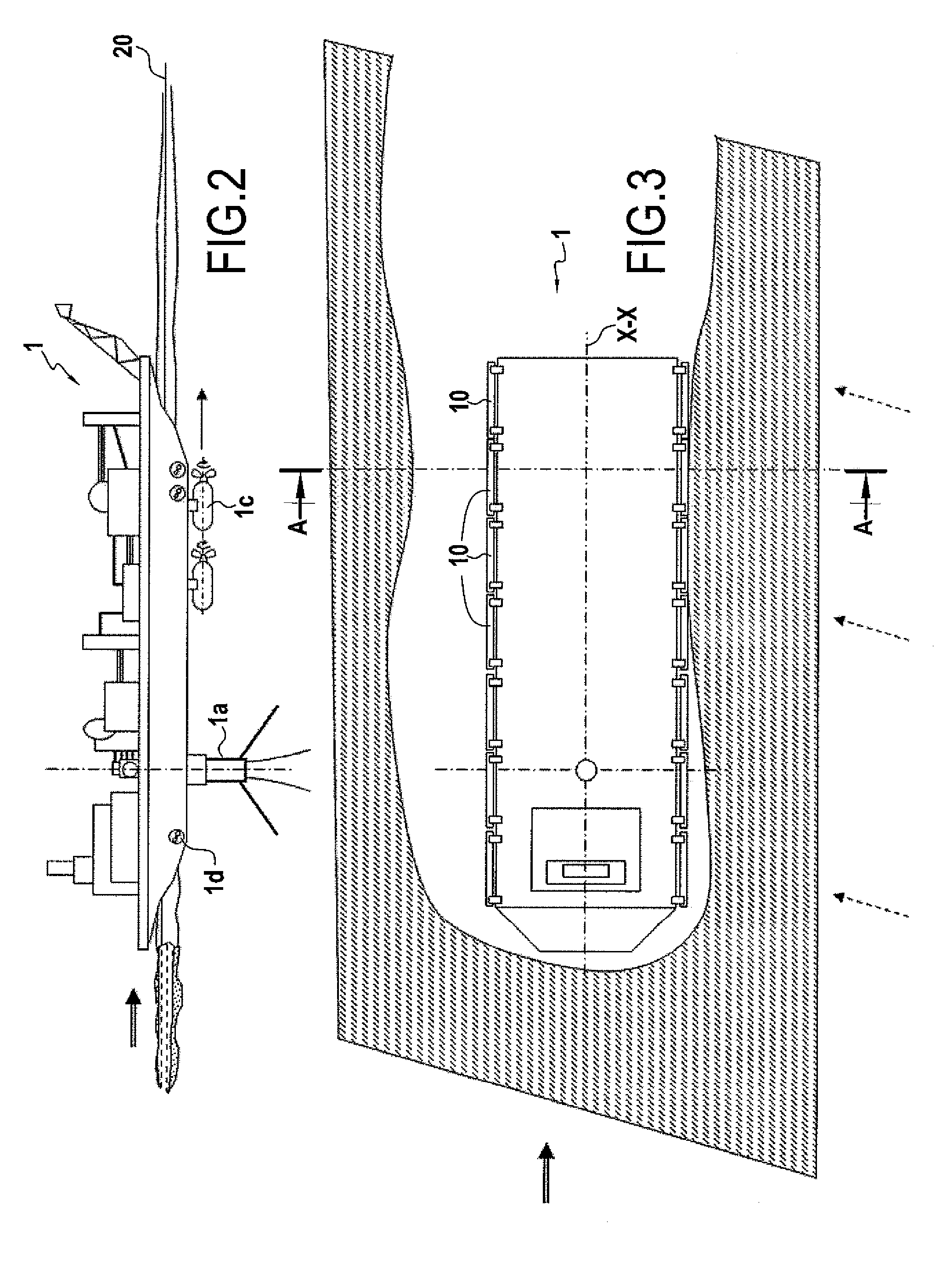
[0037]FIG. 1 is a side view, partially in section, of an FPSO type floating support or ship 1 anchored on a disconnectable turret 1a that is anchored by anchor lines 2 and connected to undersea well heads (not shown) by flexible pipes 3 in a dipping catenary configuration 3a down to a sub-surface float 4 supporting said flexible pipe, said float being held by a cable 4a that is connected to a deadman 4b on the sea bottom, with said flexible pipes 3 then continuing in a catenary configuration 3b down to the sea bottom 30, and then along the bottom to said well head. The FPSO is in cold waters in which icebergs or pack ice 5 of large area and considerably thickness move. The pack ice is generally constituted by frozen and consolidated sea water 5a of thickness that varies over the range a few tens of centimeters to several meters. From one year to another, pack ice forms from broken sheet ice associated with frozen spray that accumulates in the cold season, thereby consolidating piece...


PUM


Abstract

A floating support for off-shore oil production in an arctic or antarctic zone, the support being fitted under its hull with a disconnectable turret from which there extend anchor lines connected to the sea bottom and bottom-to-surface connection pipes. The hull including lateral sides extending in its longitudinal direction. The longitudinal lateral sides of the support carry respective pluralities of devices for localized destruction of pack ice, each device having a destruction tool having at least one pointed portion suitable for breaking pack ice by repeated actuation in vertical pivoting and / or translation of the tool relative to the side, the point, on moving downwards, thus bearing in localized manner against the surface of the pack ice with a force that is preferably at least 10,000 kN. The tool being actuated in pivoting and / or translation with the help of a pivoting and / or translation guide structure applied against the side of the support.

Description

PRIORITY CLAIM[0001]This is a U.S. national stage of application No. PCT / FR2008 / 052064, filed on Nov. 17, 2008. Priority is claimed on the following application: France Application No.: 0759681 Filed on Dec. 10, 2007, the content of which is incorporated here by reference.FIELD OF THE INVENTION[0002]The present invention relates to a floating support fitted with at least one device for localized destruction of pack ice so as to prevent the floating support from coming directly into contact with said pack ice, and thus running the risk of becoming locked in the ice.[0003]The technical field of the invention is more particularly the field of off-shore oil production in Arctic and Antarctic zones, from floating supports.[0004]A floating support for oil production generally comprises anchor means to enable it to remain in position in spite of the effects of currents, winds, and swell. In general it also includes means for drilling, storing, and processing oil and means for off-loading t...

Claims


Application Information

Patent Timeline
Patent Type & Authority Patents(United States)
IPC IPC(8): B63B35/08
CPCB63B35/12B63B35/44
Inventor DENISE, JEAN-PAUL
Owner SAIPEM SA
Learn More