Electrical connector and method of connecting twisted pair cable to the electrical connector

a technology of electrical connectors and twisted pair cables, applied in the direction of coupling device connections, coupling protective earth/shielding arrangements, electrical apparatus, etc., can solve the problems of difficult to achieve impedance matching between circuits or devices, poor and a tendency to decrease initial noise performance of shielded twisted pair cables. to achieve the effect of reducing noise performance, reducing impedance, and reducing noise performan

Active Publication Date: 2013-01-08
HIROSE ELECTRIC GROUP
View PDF20 Cites 14 Cited by
  • Summary
  • Abstract
  • Description
  • Claims
  • Application Information

AI Technical Summary

Benefits of technology

[0015]According to the first aspect of the present invention, electrical connector of the invention, the cable holding portion holds the untwisted portion of the twisted pair cable and positions the single wires of the pair at the untwisted portion so as to be parallel to each other and close or contact to each other. With the configuration, it is possible to reduce impedance at the untwisted portion, and thereby achieve impedance matching between circuits or devices that are connected via the electrical connector and twisted pair cable.
[0047]According to the invention, it is possible to control increase of the impedance or reduction of the noise performance at the untwisted portion of the twisted pair cable, especially the shielded twisted pair cable. In addition, it is possible to easily or securely connect the twisted pair cable to the electrical connector, and to shorten time required for the connecting work or to improve the yield.

Problems solved by technology

However, the unshielded twisted pair cable does not have excellent noise performance in comparison with a coaxial cable.
Accordingly, it is difficult to achieve impedance matching between circuits or devices, which are connected via the conventional electrical connector and the twisted pair cable.
Furthermore, when the single wires are untwisted or the conductive shield is removed, initial noise performance of the twisted pair cable tends decrease at the end portion of the twisted pair cable connected to the conventional electrical connector.
According to Patent Reference, in case of a small-sized electrical connector or in case of connecting a plurality of twisted pair cable (a plurality of paired wires) to one electrical connector at small intervals, it is not easy to bundle the untwisted pair of single wires with the tape or the tube.
As a result, according to the technique described in Patent Reference, it is difficult to connect the conventional electrical connector to the twisted pair cable in a simple procedure, and it is necessary to take more time for the connection work.
Further, it may result in poor yield due to poor attachment of the tape or the tube.

Method used


Image

  • Electrical connector and method of connecting twisted pair cable to the electrical connector
  • Electrical connector and method of connecting twisted pair cable to the electrical connector
  • Electrical connector and method of connecting twisted pair cable to the electrical connector

Examples


first embodiment

(First Embodiment)

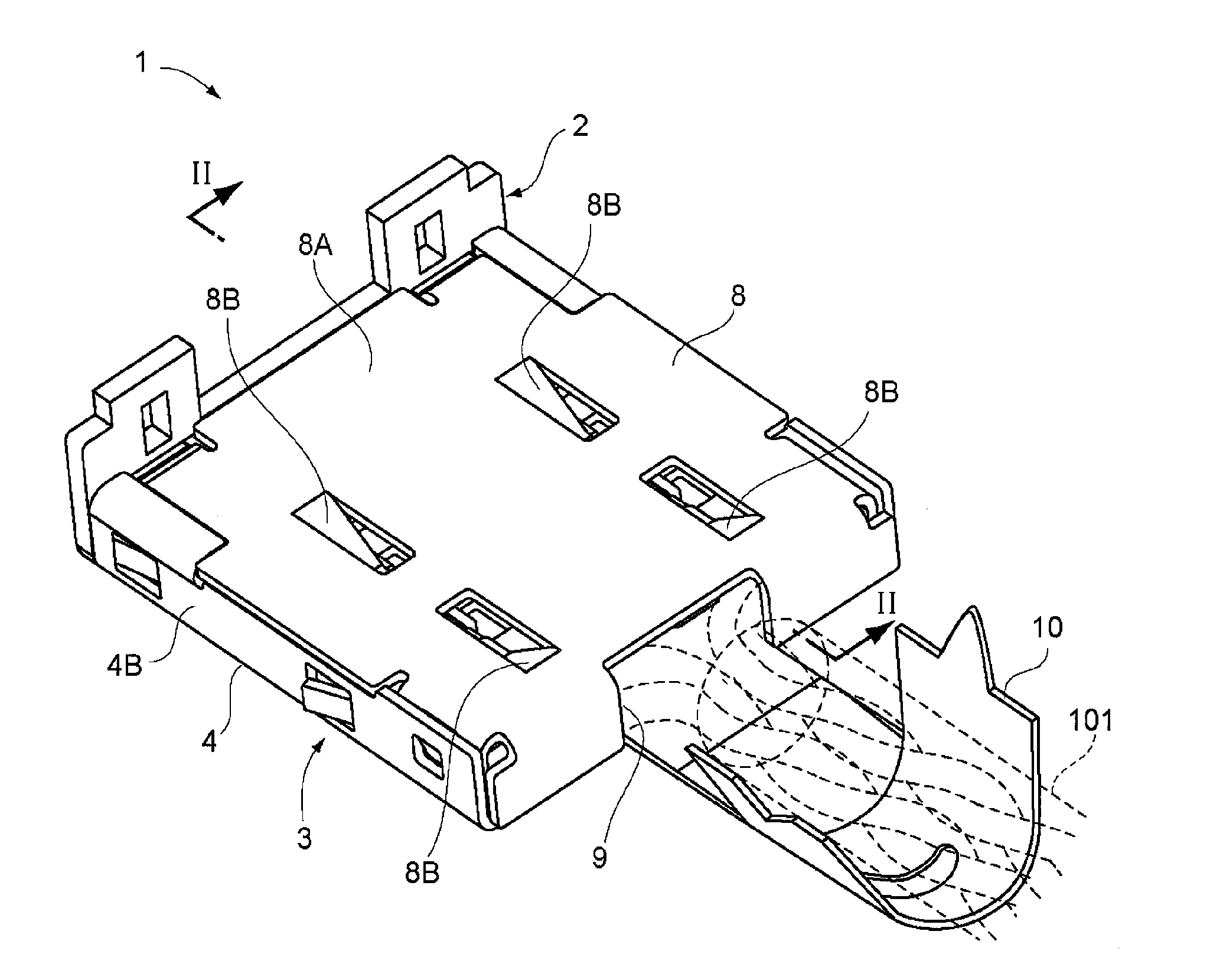
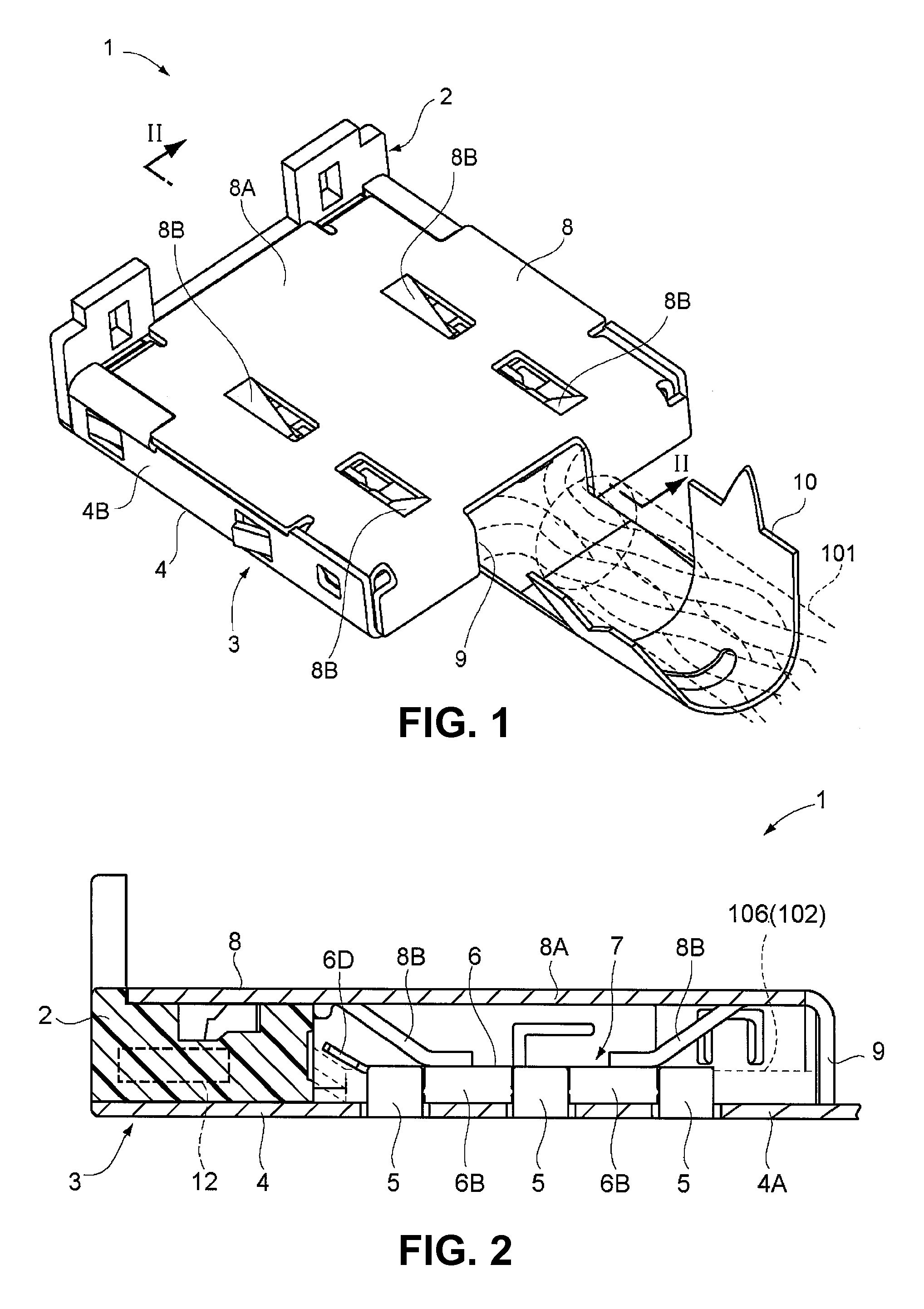
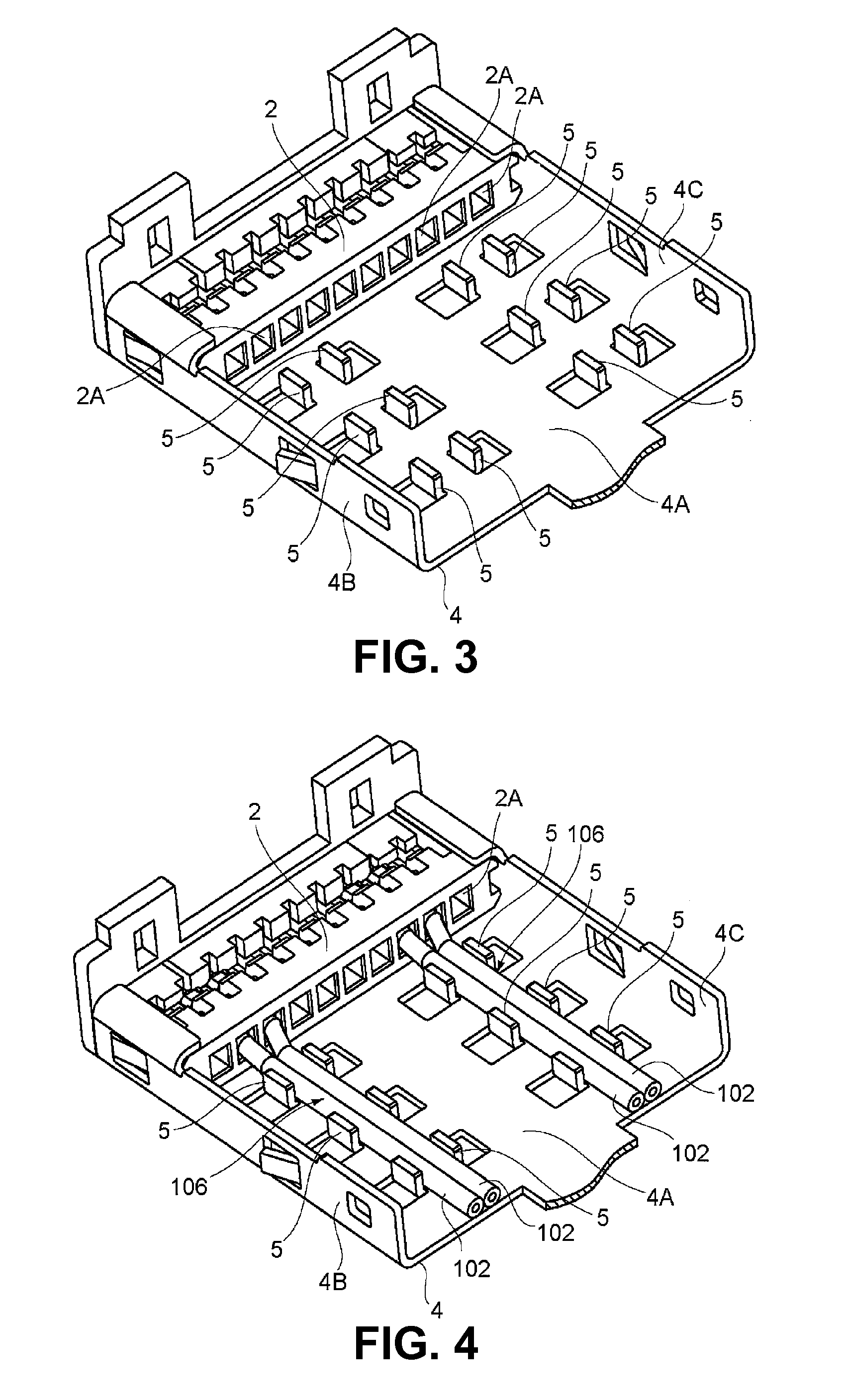
[0068]First, an electrical connector according to a first embodiment of the invention will be described. FIGS. 1 and 2 show an electrical connector according to the first embodiment of the invention. On the other hand, FIGS. 8 and 9 show a shielded twisted pair cable to be connected to the electrical connector of FIG. 1.

[0069]The electrical connector 1 according to a first embodiment of the invention is an electrical connector to connect to an end portion of a shielded twisted pair cable 101. As shown in FIG. 8, the shielded twisted pair cable 101, which is described as an example in the embodiment, has two twisted wire pairs made by twisting a pair of single wires 102 together. Furthermore, the shielded twisted pair cable 101 has a drain wire 103 for each twisted wire pair, and each twisted wire pair is covered together with the drain wire 103 by a conductive coating film 107.

[0070]In addition, the two twisted wire pairs respectively covered together with the drai...

second embodiment

(Second Embodiment)

[0104]Next, an electrical connector according to a second embodiment of the invention will be described. FIG. 10 shows an electrical connector according to the second embodiment of the invention, which is in the middle of connecting the shielded twisted pair cable. Here, in FIG. 10, the same reference numerals are used to the same elements as those of the electrical connector 1 of the first embodiment and the explanation will be omitted.

[0105]In FIG. 10, the electrical connector 21 according to the second embodiment of the invention has lanced sections provided on the bottom plate portion 4A of the base portion 4 so as to continuously extend from a basal end section of the base portion 4 to a position right before the connector main body 2. In addition, each lanced section 22 is formed to have a V-shaped lateral section.

[0106]Prior to disposing the untwisted portion 106, upper ends of the lanced sections 22 are away from each other as in a pair of lanced sections ...

third embodiment

(Third Embodiment)

[0110]Next, an electrical connector according to the third embodiment of the invention will be described. FIG. 11 shows the electrical connector according to the third embodiment of the invention, which is in the middle of connecting to a shielded twisted pair cable. Here, in FIG.

[0111]11, the same reference numerals are used for the same elements as those in the electrical connector 1 according to the first embodiment and the explanation will be omitted.

[0112]While each lanced section 22 of the electrical connector 21 according to the second embodiment of the invention is configured to clamp the both sides of the untwisted portion 106 in the width direction, each lanced section 32B of the electrical connector 31 according to the third embodiment of the invention shown in FIG. 11 is configured to surround the untwisted portion 106 from one side to the other in the width direction.

[0113]More specifically, in the electrical connector 31, the lanced sections that cove...


PUM


Abstract

An electrical connector includes a connector main body made of an insulating material for attaching an end portion of a pair of single wires untwisted at an end portion of a twisted pair cable; and a shell member to hold the untwisted portion. The shell member includes a base portion made of a conductive material to dispose the connector main body at the front end side and the untwisted portion at the basal end side; a cable holding portion made of a conductive material to hold the single wires at the untwisted portion for positioning the single wires parallel to each other and close or contact to each other; and a cover portion provided on the base portion to have at least the untwisted portion and the cable holding portion between the cover portion and base portion.

Description

BACKGROUND OF THE INVENTION AND RELATED ART STATEMENT[0001]The present invention relates to an electrical connector to be connected to a twisted pair cable and a method of connecting a twisted pair cable to the electrical connector.[0002]In general, there are two types of twisted pair cable, i.e., an unshielded twisted pair cable (UTP) and a shielded twisted pair cable (STP). The unshielded twisted pair cable is a cable made by twisting a pair of single wires. As compared with a simple parallel cable, the unshielded twisted pair cable is not susceptible to noises from outside and has good noise performance with less noise radiation. Further, the unshielded twisted pair cable is easy to handle and reasonable priced. Accordingly, the unshielded twisted pair has been widely used. However, the unshielded twisted pair cable does not have excellent noise performance in comparison with a coaxial cable. For this reason, the shielded twisted pair cable, which is made by twisting a pair of si...

Claims


Application Information

Patent Timeline
Patent Type & Authority Patents(United States)
IPC IPC(8): H01R13/648
CPCH01R9/035H01R13/6589H01R13/6473H01R13/65915
Inventor NAGAWATARI, TAKASHINAKATA, NAOHISAKUBOTA, TADASHI
Owner HIROSE ELECTRIC GROUP
Why Eureka
Try Eureka