Method and in-vehicle device for correcting alignment information representative of the alignment of an in-vehicle camera

a technology of in-vehicle camera and alignment information, which is applied in the field of correcting alignment information, can solve the problem that a laser, in addition to a camera, needs to be provided in the vehicl

Active Publication Date: 2013-01-08
ALPINE ELECTRONICS INC
View PDF6 Cites 9 Cited by
  • Summary
  • Abstract
  • Description
  • Claims
  • Application Information

AI Technical Summary

Benefits of technology

[0012]The alignment information generated by the correction unit in the in-vehicle device may be used in various types of processing in which an image captured by a camera is used. That is, for example, when a bird's eye view image display unit that generates and displays a bird's eye view image showing how the surroundings of the vehicle are observed from a position above the vehicle is provided in the in-vehicle device so that the bird's eye view image display unit can generate the bird's eye view image by performing view transformation on the image captured by the camera on the basis of the alignment information generated by the correction unit, a bird's eye view image showing the surroundings can be accurately generated.
[0017]According to the present embodiments, alignment information that represents the alignment, such as a position and a posture, of a camera installed in a vehicle can be corrected in a non-complex arrangement.

Problems solved by technology

In the technique disclosed in Japanese Unexamined Patent Application Publication No. 2003-274394 for correcting a change in the angle of depression of a camera, a problem exists in that a laser, in addition to a camera, needs to be provided in a vehicle.

Method used


Image

  • Method and in-vehicle device for correcting alignment information representative of the alignment of an in-vehicle camera
  • Method and in-vehicle device for correcting alignment information representative of the alignment of an in-vehicle camera
  • Method and in-vehicle device for correcting alignment information representative of the alignment of an in-vehicle camera

Examples


Embodiment Construction

[0026]An exemplary embodiment of the present invention will now be described.

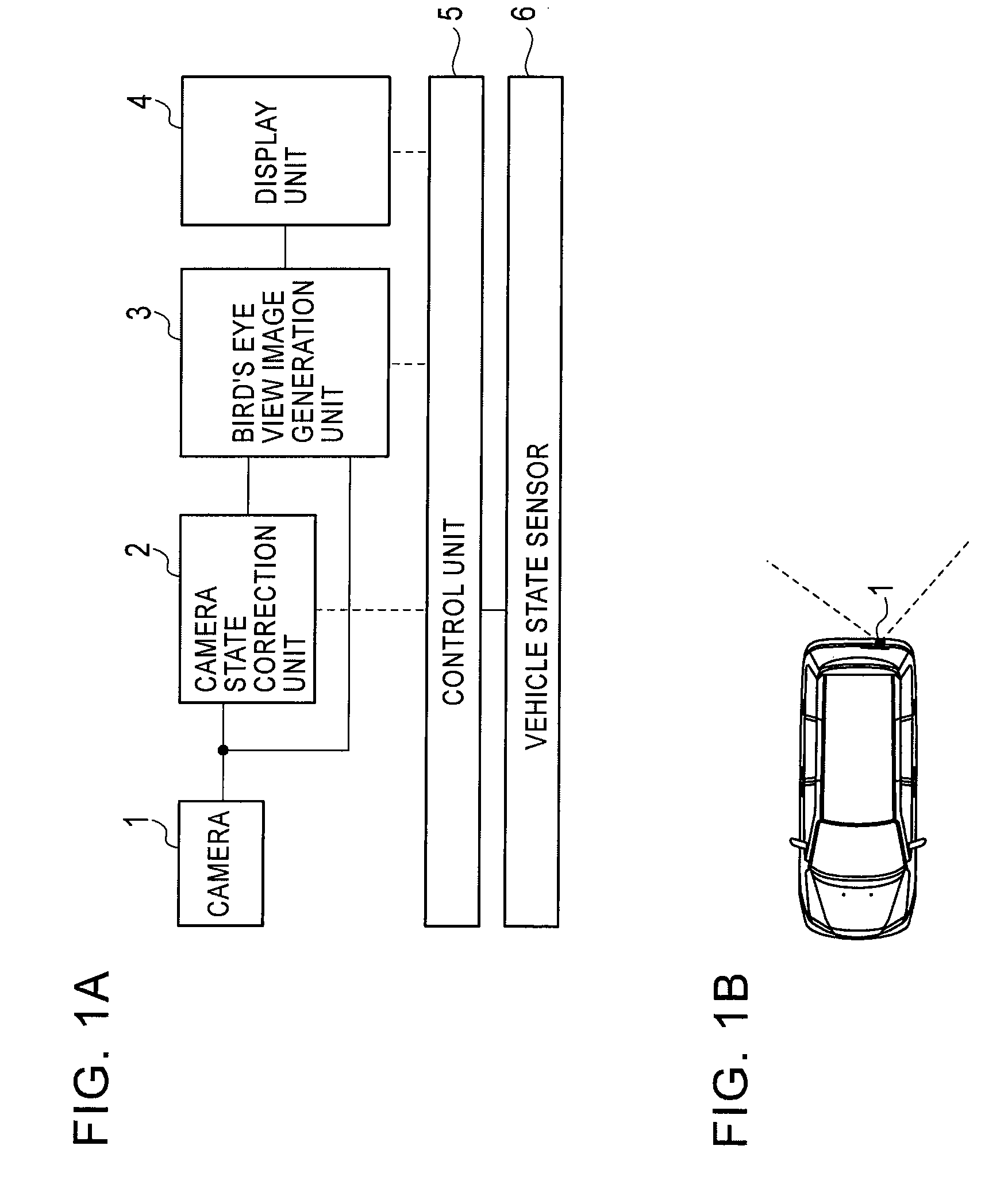
[0027]FIG. 1A shows the components of a surrounding monitoring device according to the exemplary embodiment.

[0028]The surrounding monitoring device includes a camera 1, a camera state correction unit 2, a bird's eye view image generation unit 3, a display unit 4, a control unit 5, and a vehicle state sensor 6, as shown in the drawing.

[0029]The surrounding monitoring device may be constructed with a computer as hardware, the computer including, for example, a microprocessor, a memory, and other peripherals. In this case, the camera state correction unit 2 and the bird's eye view image generation unit 3 may be implemented by the microprocessor executing predetermined computer programs.

[0030]The vehicle state sensor 6 is a sensor that detects various states of a vehicle, for example, the speed of the vehicle, the state of braking by a parking brake, a steering angle, and an angular speed.

[0031]The camera 1 is ...


PUM


Abstract

A process is repeated in which N state vectors each including, as elements, the position of a camera with respect to a vehicle, the posture of the camera, the width of a lane where the vehicle is driving, and the orientation of the vehicle with respect to the lane are changed according to a predetermined dynamics model, a reference state vector representing the positions of edges of lane marks included in an image captured by the camera is generated when each of the changed state vectors is true, considering the positions of edges of lane marks in the image as an observation vector, the degree of match between the reference state vector and the observation vector is calculated as the weight of the state vector, a weighted average vector of the state vectors is calculated, and N state vectors are resampled on the basis of the calculated weights.

Description

RELATED APPLICATIONS[0001]The present application claims priority to Japanese Patent Application Number 2008-142148, filed May 30, 2008, the entirety of which is hereby incorporated by reference.BACKGROUND[0002]1. Field of the Invention[0003]The present invention relates to a technique for correcting alignment information that represents the alignment, such as a position and a posture, of a camera installed in a vehicle.[0004]2. Description of the Related Art[0005]One of the known techniques for correcting alignment information that represents the alignment, such as a position and a posture, of a camera installed in a vehicle is a technique for, in a device that generates and displays a bird's eye view image showing the surroundings of a vehicle, capturing, with a camera, an image formed by a laser beam projected onto a road surface from a laser installed in a vehicle and correcting the angle of depression of the camera on the basis of the captured image (for example, Japanese Unexa...

Claims


Application Information

Patent Timeline
Patent Type & Authority Patents(United States)
IPC IPC(8): H04N7/18
CPCB60R1/00G06K9/00798G06K9/00812B60R2300/607G06V20/588G06V20/586
Inventor MORI, DAISHI
Owner ALPINE ELECTRONICS INC
Why Eureka
Try Eureka