
Sharpener with autostop feature

a technology of automatic stop and pencil, which is applied in the field of pencil sharpeners, can solve the problems of excessive wear and waste of pencils, particularly acute, lack of experience, judgment, and/or adequate hand/eye coordination

Active Publication Date: 2013-01-15
SANFORD LP
View PDF11 Cites 16 Cited by
  • Summary
  • Abstract
  • Description
  • Claims
  • Application Information

AI Technical Summary

Benefits of technology

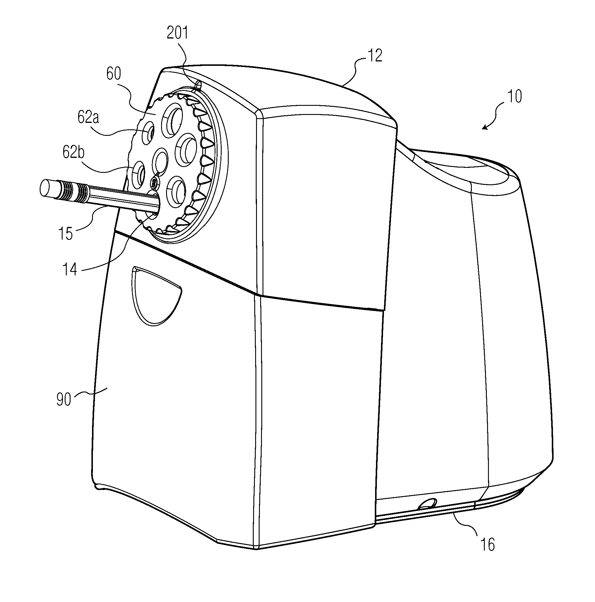
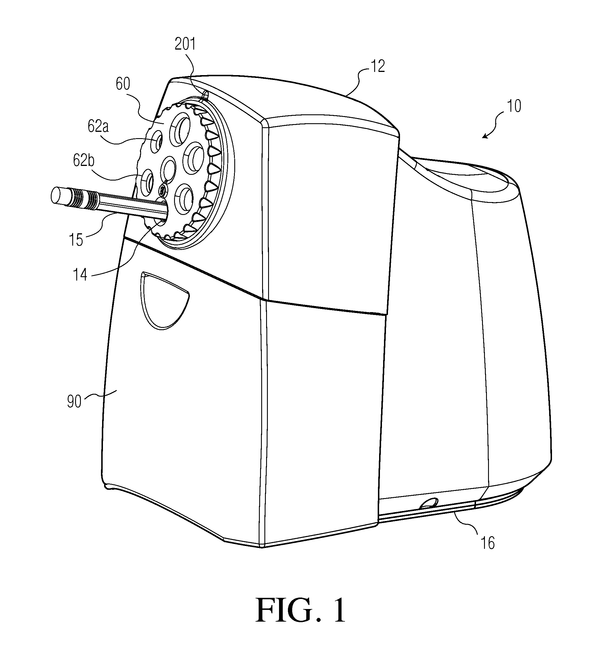
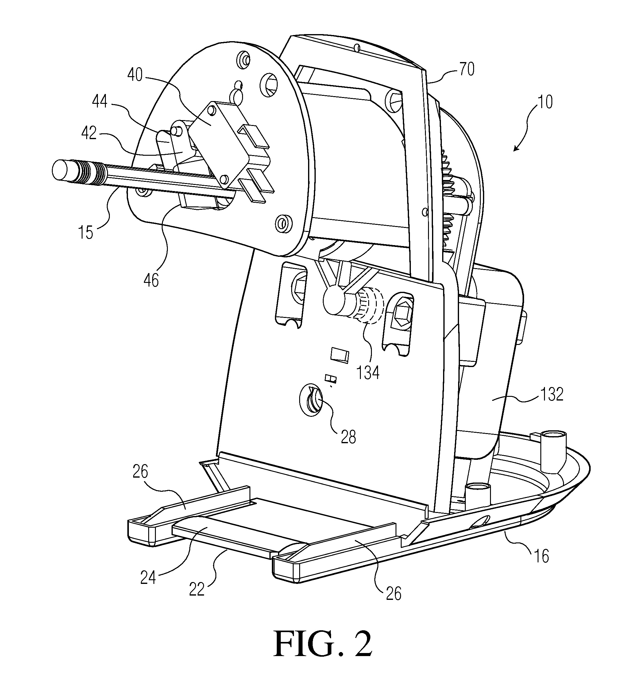
The present invention provides an electric pencil sharpener with a motor, cutter assembly, and switch assembly. The cutter assembly includes a conical housing with a conical cavity for receiving a pencil, and at least one rotary blade with spiral cutting edges for sharpening the pencil. The switch assembly includes a shutoff switch and mechanical means for actuating it when a desired degree of sharpening has been achieved. The electronic control unit delays the deactivation of the motor for a predetermined period of time. The invention allows for efficient and effective sharpening of pencils.

Problems solved by technology

While such pencil sharpeners are easy to use, they can quickly cause excess wear and waste of the pencil, i.e., by oversharpening.
This problem is particularly acute with children lacking experience, judgment, and / or adequate hand / eye coordination.
However, these stops are sometimes difficult to sense, especially for children.
However, a significant disadvantage of this system is that it is not well understood by many users of such systems.
Additionally, because the motor keeps running the sharpener continues to produce unwanted noise, which is problematic in the office and classroom environments.
If the switch is actuated too early, the indicator will illuminate before sharpening is complete and if the switch mechanism is placed too far back in the pencil bore, it may not function at all.

Method used


Image

  • Sharpener with autostop feature
  • Sharpener with autostop feature
  • Sharpener with autostop feature

Examples


Embodiment Construction

[0021]Exemplary embodiments of the present invention are now described with reference to the Figures. Reference numerals are used throughout the detailed description to refer to the various elements and structures. In other instances, well-known structures and devices are shown in block diagram form for purposes of simplifying the description. Although the following detailed description contains many specifics for the purposes of illustration, a person of ordinary skill in the art will appreciate that many variations and alterations to the following details are within the scope of the invention. Accordingly, the following embodiments of the invention are set forth without any loss of generality to, and without imposing limitations upon, the claimed invention.

[0022]The present invention relates to an electric pencil sharpener that includes features for preventing the oversharpening of a pencil or similar item (i.e., a cosmetics item). In one or more exemplary embodiments, the feature...


PUM


Abstract

An electric pencil sharpener comprising a motor; a cutter assembly operatively connected to the motor, wherein the cutter assembly further includes: a conical housing defining a conical cavity therein for receiving a pencil; and at least one rotary blade mounted in close proximity to the conical cavity, wherein the at least one rotary blade further includes spiral cutting edges for sharpening the pencil; a switch assembly positioned at the narrow end of the conical housing, wherein the switch assembly further includes: a shutoff switch operative to deactivate the motor; mechanical means for actuating the shutoff switch when a desired degree of sharpening has been achieved by the cutter assembly; and an electronic control unit in electrical communication with the switch assembly and the motor, wherein the electronic control unit is operative to provide a delay of a predetermined period of time between when the shutoff switch is activated and when the motor is deactivated.

Description

CROSS-REFERENCE TO RELATED APPLICATIONS[0001]This patent application claims the benefit of U.S. Provisional Patent Application Ser. No. 61 / 221,221 filed on Jun. 29, 2009 and entitled “Sharpener with Autostop Feature,” the disclosure of which is hereby incorporated by reference herein in its entirety and made part of the present U.S. utility patent application for all purposes.BACKGROUND OF THE INVENTION[0002]The present invention relates generally to pencil sharpeners, and more specifically to a pencil sharpener that includes an automatic stop (i.e., shut off) feature.[0003]Manually operated and electrically powered pencil sharpeners are commonplace in modern society. When a pencil is inserted through a pencil-receiving opening of a pencil sharpener's housing, the pencil enters a sharpening assembly which cuts an outer layer of wood to expose and sharpen an inner core of lead or graphite. Some manual pencil sharpeners include a selector guide. The selector guide typically includes s...

Claims


Application Information

Patent Timeline
IPC IPC(8): B43L23/00
CPCB43L23/00B43L23/008B43L23/02
Inventor SCHUMACHER, MICHAELDUNLAP, BENMUIR, THEO
Owner SANFORD LP
Learn More