Rotor slippage complementary exciting permanent-magnetic brushless variable speed motor

A permanent magnet brushless, variable speed motor technology, applied in the fields of magnetic field/electric field shielding, electrical components, electromechanical devices, etc., can solve the problems of adding excitation windings and circuits, complex motor structure, and easy failure, to ensure continuous change, Guaranteed speed/torque characteristics, easy moving effect

Inactive Publication Date: 2011-05-18
杨荷
View PDF6 Cites 17 Cited by
  • Summary
  • Abstract
  • Description
  • Claims
  • Application Information

AI Technical Summary

Problems solved by technology

Using an electronic controller to weaken the magnetic field, the current consumption is large, and the volume is large, resulting in higher energy consumption and production costs, which will inevitably increase the production cost of the enterprise and increase the economic burden of the user.
Moreover, the cold and heat resistance of the electronic controller is weak, and it is prone to failure when working in different environments.
The other is the method of compound excitation using current and permanent magnets. This kind of motor increases the excitation winding and circuit, and also consumes power
For example, the CLC number: TM301.2, TM351 document code: A, article number: 1007-7162 (2004) 04-0001-04 "Application of New Adjustable Magnet Permanent Magnet Brushless DC Motor in Electric Vehicles" As mentioned, due to the complex structure of the motor using this method, the cost increases and other factors, the technical effect is also unsatisfactory

Method used


Image

  • Rotor slippage complementary exciting permanent-magnetic brushless variable speed motor
  • Rotor slippage complementary exciting permanent-magnetic brushless variable speed motor
  • Rotor slippage complementary exciting permanent-magnetic brushless variable speed motor

Examples


Embodiment Construction

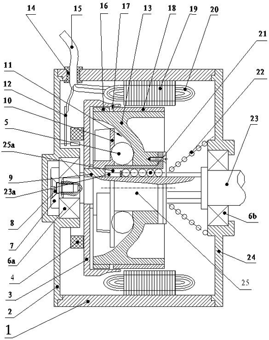
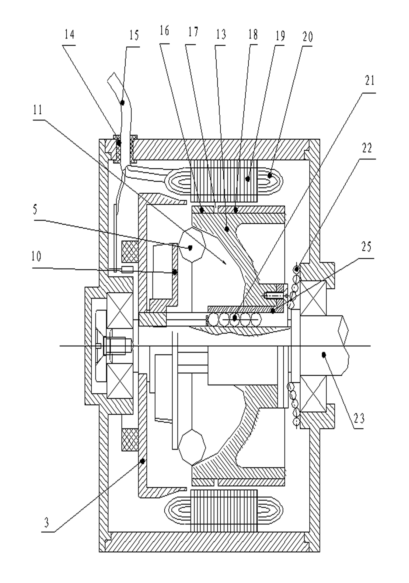
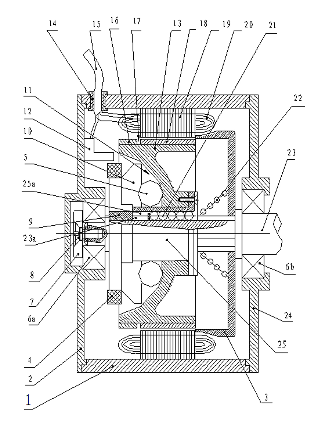
[0037] see figure 1 , figure 2 The casing 1 of the rotor slipping complementary excitation permanent magnet brushless variable speed motor of the present invention is connected with the front end cover 2 and the rear end cover 24 to form a frame, and the front end cover 2 and the rear end cover 24 are connected and fixed with the casing 1 by screws. The stator composed of windings 20 and iron core 19 is arranged on the inner cavity circumference of the casing 1, and the outgoing cable 15 of the winding 20 passes through the ferrule 14 provided on the casing 1 to support the rotor 13 and output the rotor. The motor rotating shaft 23 of torque is supported on the front end cover 2 by the bearing 6a, is supported on the rear end cover 24 by the bearing 6b, and one end of the motor rotating shaft 23 stretches out the rear end cover 24 for outputting power to the transmission mechanism. The bearing 6a is positioned by the baffle 7 and the shoulder of the motor shaft 23, and the b...


PUM


Abstract

The invention discloses a rotor slippage complementary exciting permanent-magnetic brushless variable speed motor. A rotor of the motor is connected with a motor rotating shaft through a spline and can move along the axial direction; two groups of polarity-complementation exciting magnetic sources are arranged on the periphery of the rotor side by side, wherein one group is main flux source exciting bodies, and the other group is secondary flux source exciting bodies; the main and the secondary flux source exciting bodies are arranged with alternated polarities by permanent magnets with the same number respectively to form rings; the polarity distribution on the circumference of the secondary flux source exciting bodies is spaced by one polar distance from the polarity distribution on the circumference of the main flux source exciting bodies; a roller path disc is fixedly connected on the motor rotating shaft, and the roller path disc and a conical cavity at one end of the rotor form a wedge-shaped space; and a plurality of rollers for pushing the rotor to move along the axial direction by eccentric motion are arranged in the wedge-shaped space. In the invention, the rotor moves along the axial direction to reduce the flux so as to change the torque/rotational speed property of the motor and realize speed variation, which improves the mechanical property of the permanent-magnetic brushless variable speed motor per se, enlarges the full-power speed adjusting range of the motor, keeps the volume of the motor and saves the production cost.

Description

technical field [0001] The invention relates to a permanent magnet brushless motor, in particular to a rotor slipping complementary excitation permanent magnet brushless variable speed motor designed for electric drive of electric vehicles and machine tools. Background technique [0002] In the existing technologies and products, the driving motors used as electric power mainly include induction motors (IM), permanent magnet brushless motors (PLDCM), permanent magnet synchronous motors (PMSM) and switched reluctance motors (SRM). Induction motors and switched reluctance motors, permanent magnet brushless motors (PLDCM) are compact in structure, have the largest specific power in volume and weight, high efficiency, easy manufacture and maintenance, and are used more and more. However, due to the use of permanent magnets for excitation, this kind of motor is difficult to adjust the magnetic flux under the existing structure, and cannot adjust the speed with constant power. Th...

Claims


Application Information

Patent Timeline
Patent Type & Authority Applications(China)
IPC IPC(8): H02K29/08H02K1/27H05K9/00
Inventor 杨荷
Owner 杨荷
Why Eureka
Try Eureka