Steering cylinder mounting arrangement used with a length-adjustable axle

a technology of steering cylinder and mounting arrangement, which is applied in the direction of convertible cycles, transportation and packaging, and cycles, etc., can solve the problems of changing the distance between the steering arm at the top of the caster spindle and the fixed steering cylinder, and no provision, so as to improve the access to the machine, avoid interference, and improve the effect of access to other parts

Active Publication Date: 2013-01-15
DEERE & CO
View PDF10 Cites 17 Cited by
  • Summary
  • Abstract
  • Description
  • Claims
  • Application Information

AI Technical Summary

Benefits of technology

[0006]A broad object of the invention is to provide a steering cylinder mounting assembly comprising a reaction arm mounted for movement with the adjustable section of the fixed rear axle so that the distance between the actuator and the steering arm remains constant and with the reaction arm being adjustable to any angular position about the caster-mounted wheel spindle so as to accommodate different track positions of the steered rear wheels and / or different machine configurations and / or improved access to the machine without interference with other parts, other attachments, or for any other reasons.
[0008]In accordance with a second embodiment, it is an object to mount the reaction arm to the spindle of the steered wheel in a manner which permits the reaction arm to be placed in an infinite number of positions about the spindle so as to provide improved access to other parts and / or avoid interference with other parts as changes are made in the track width of the steered rear wheels and / or to adapt to different machine configurations.

Problems solved by technology

A drawback of this assist system is that, while the rear axle is disclosed as being adjustable in length, no provision is made for adjusting the position of the steering assist cylinder in order to accommodate for the change in axle length, and, hence, the change in the distance between the steering arm at the top of the caster spindle and the fixed steering cylinder.

Method used


Image

  • Steering cylinder mounting arrangement used with a length-adjustable axle
  • Steering cylinder mounting arrangement used with a length-adjustable axle
  • Steering cylinder mounting arrangement used with a length-adjustable axle

Examples


Embodiment Construction

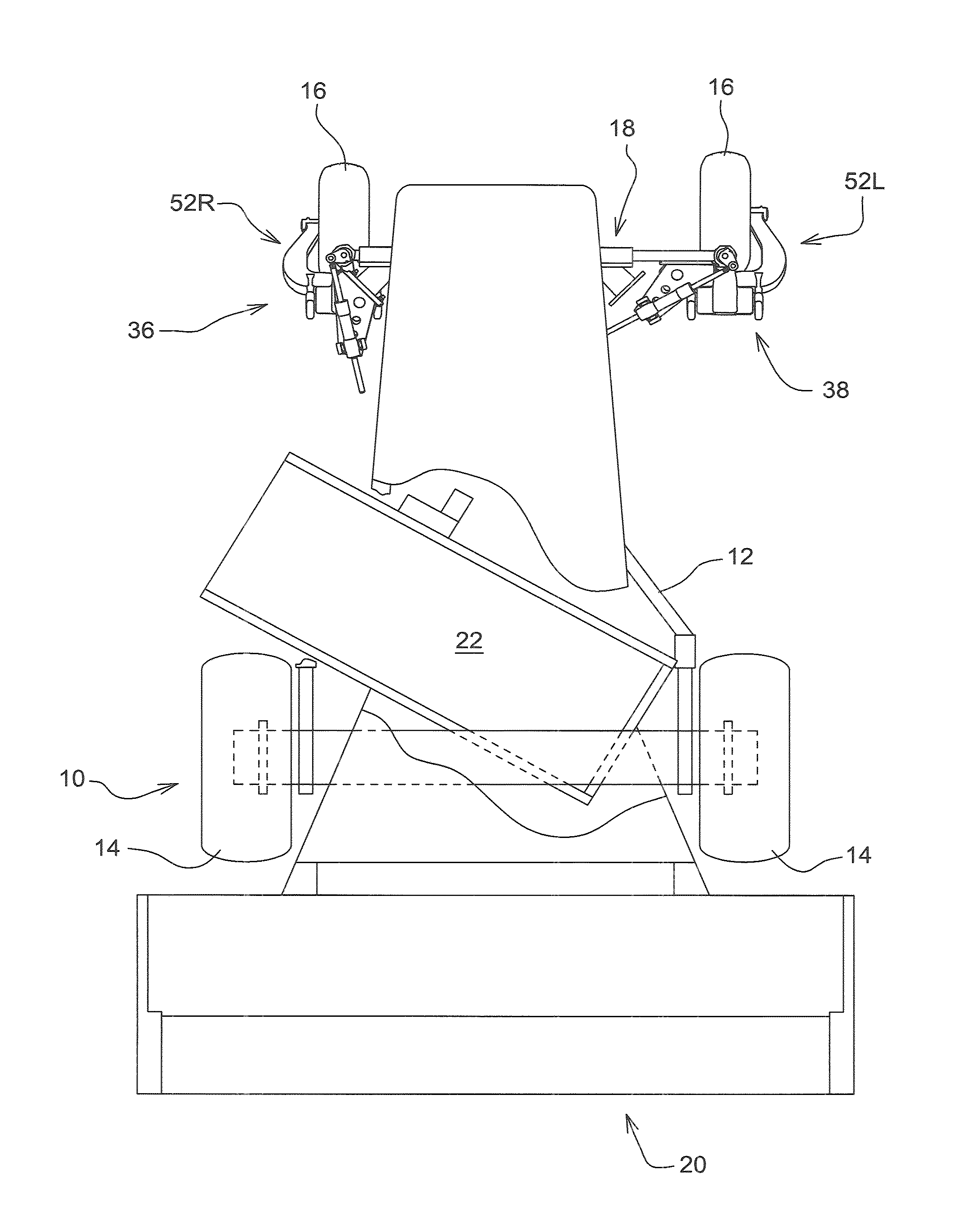
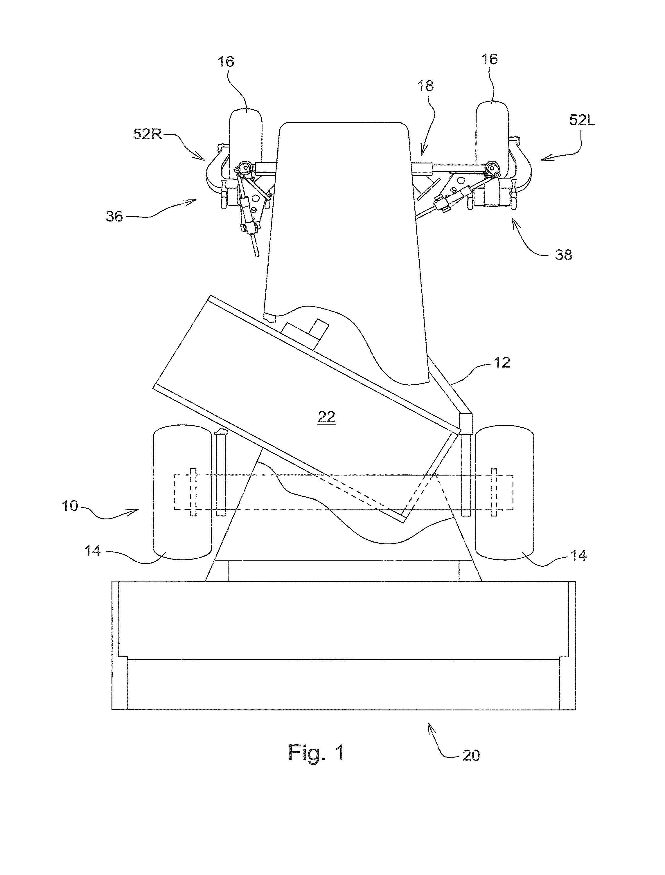
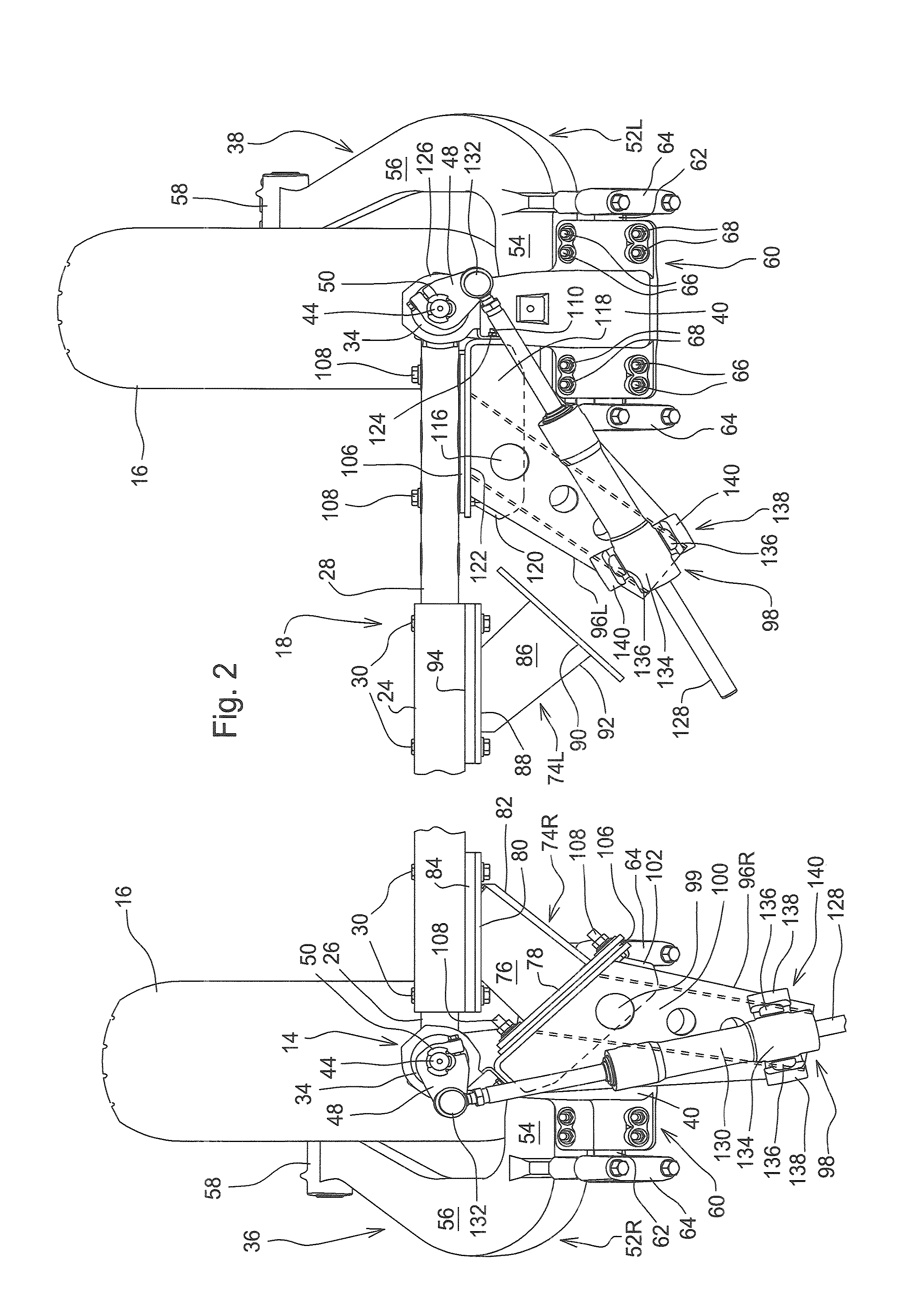
[0016]Referring now to FIG. 1, there is shown a self-propelled windrower 10 including a main frame 12 supported on a pair of driven front wheels 14 and on a pair of rear ground wheels 16 located at the opposite ends of an axle 18 located at the rear of the frame 12. A header 20 is suspended at a forward end of the frame 12 in a well known manner (not shown), with the header being equipped with crop cutting and conditioning arrangements (not shown), with the cutting arrangement being operable for severing stems of the crop at ground level and for feeding the severed crop into the conditioning arrangement which conditions and then propels the conditioned crop to the rear. A cross-conveyor 22 is suspended from the frame 12 in a conventional manner (not shown) so as to extend obliquely to a longitudinal center line of the windrower 10 from a location just inside the left front wheel 14 to a location just to the rear of the right front wheel 14, the conveyor 22 being mounted for selectiv...


PUM


Abstract

A windrower having an adjustable axle to vary a width of steerable caster-mounted rear wheels operably connected by right and left steering cylinders mounted to right and left reaction arms pivoted to respective rods coupled to steering arms fixed to respective spindles mounted within a cylindrical receptacle at outer ends of the adjustable axle. One embodiment each reaction arm has a bracket coupled to a fixed portion of the rear axle when telescopic end sections of the axle are in a narrow width position, and selectively mounted to outer ends of the telescopic end sections of the axle when in a wide width position. A second embodiment has the reaction arms mounted to spindle receptacles at outer ends of the axle sections to provide the reaction arms with an infinite number of angular positions about the spindle receptacles for different tread widths of the steered rear wheels.

Description

FIELD OF THE INVENTION[0001]The present invention relates to steering cylinder mountings and more specifically relates to such mountings as are applied for steering wheels at the opposite ends of an axle which is adjustable to vary the tread of the vehicle.BACKGROUND OF THE INVENTION[0002]Self-propelled windrowers typically include a main frame supported on a pair of front wheels, which are separately driven hydrostatically so as to afford steering to the windrower by driving the wheels at different speeds, and a pair of rear wheels which are mounted to opposite ends of a rear axle so that they pivot about an upright caster axis. Some windrowers are capable of delivering conditioned crop to one side of the vehicle to form a windrow in a region which may be located at least partially in the track behind the front wheel at that side of the vehicle in order to group the windrow with a previously formed windrow laid down along a path at the center of the vehicle between the front and re...

Claims


Application Information

Patent Timeline
Patent Type & Authority Patents(United States)
IPC IPC(8): B62D61/00B60K17/30B62D5/06B62D55/084B62B3/02
CPCB60B35/10B62D5/12B62D9/00
Inventor GEIGER, DAVID W.PARSONS, STEPHEN K.CHOBHE, SHIRISHKUMAR JALINDERNATH
Owner DEERE & CO
Why Eureka
Try Eureka