
Semiconductor device and method for manufacturing the same

a technology of semiconductor devices and semiconductors, applied in semiconductor devices, semiconductor/solid-state device details, instruments, etc., can solve problems such as poor connection, poor connection, and poor connection, and achieve the effect of suppressing poor connection or increasing contact resistan

Inactive Publication Date: 2013-01-15
SEMICON ENERGY LAB CO LTD
View PDF25 Cites 1 Cited by
  • Summary
  • Abstract
  • Description
  • Claims
  • Application Information

AI Technical Summary

Benefits of technology

[0009]In view of the foregoing problem, it is an object of the present invention to suppress poor connection or increase in contact resistance even in the case where an antenna is formed over an integrated circuit portion.
[0014]According to the present invention, poor connection or increase in contact resistance can be suppressed even in the case where an antenna is formed over an integrated circuit portion.

Problems solved by technology

Connection between a fine terminal of the integrated circuit portion and the antenna is accompanied by technical difficulty, resulting in reduction of yield.
Further, stress is applied to a connection point when the semiconductor device is used, which becomes a cause of disconnection or poor connection.
In particular, it is expected that poor connection is problematic in the case of using a flexible semiconductor device.
As a result, poor connection between the integrated circuit portion and the conductive film serving as an antenna or increase in contact resistance therebetween may be a concern.
Further, in the case where the integrated circuit portion is layered, a problem of poor connection may occur which is caused by increase in depth of an opening through which the integrated circuit portion and the conductive film serving as an antenna are connected to each other.

Method used


Image

  • Semiconductor device and method for manufacturing the same
  • Semiconductor device and method for manufacturing the same
  • Semiconductor device and method for manufacturing the same

Examples


embodiment mode 1

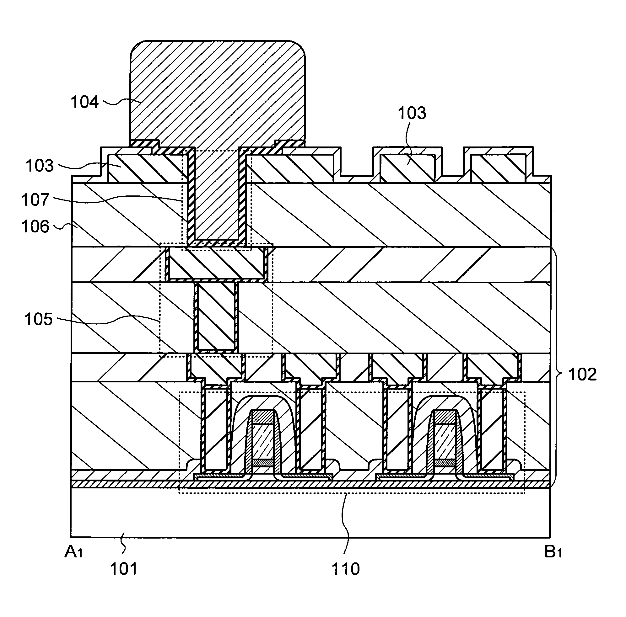
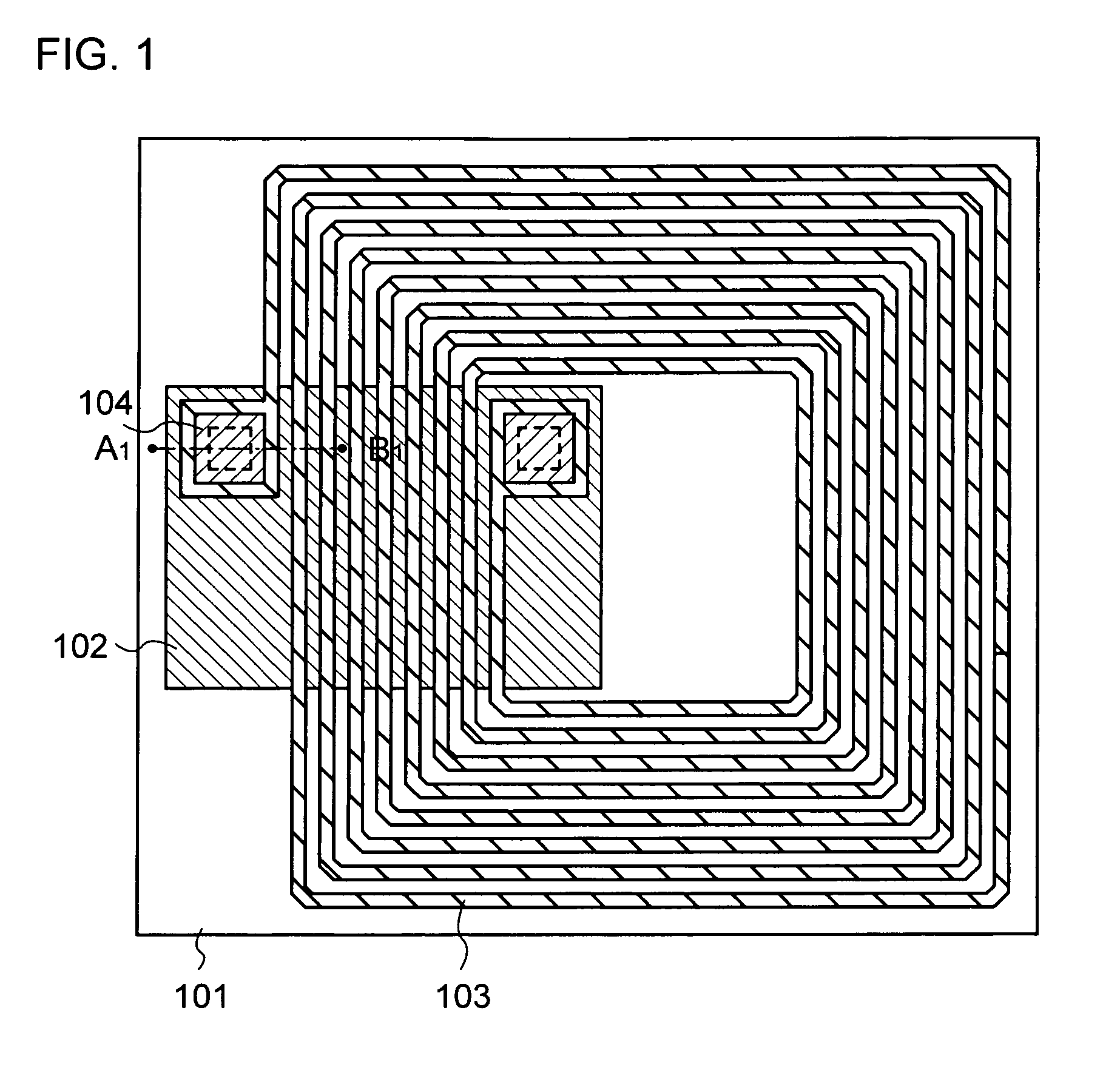
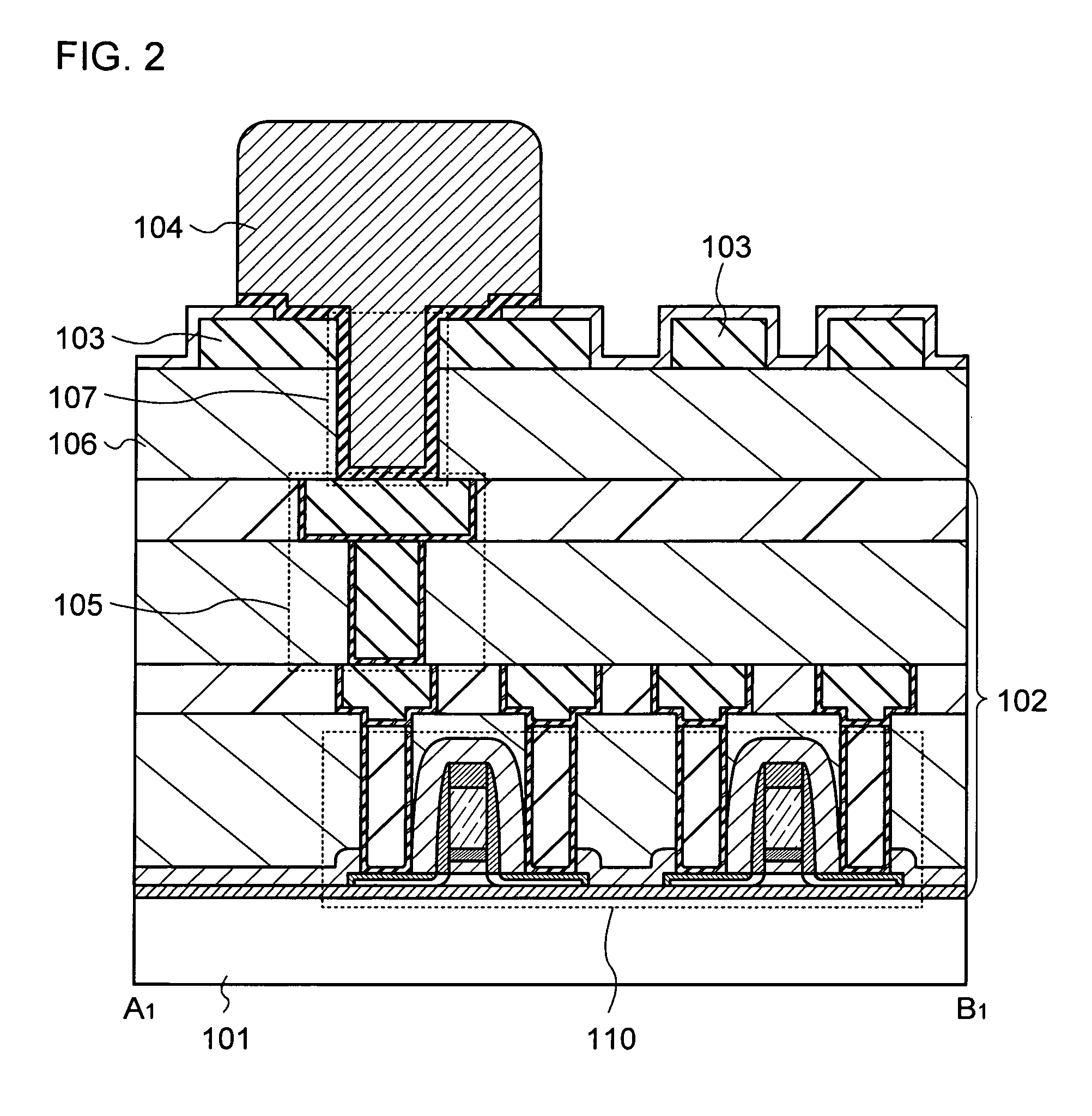
[0035]This embodiment mode describes an example of a semiconductor device of the present invention with reference to the drawings. In the description below, FIG. 1 shows a top surface of a semiconductor device and FIG. 2 is a cross-sectional view taken along line A1-B1 of FIG. 1.

[0036]A semiconductor device described in this embodiment mode includes an integrated circuit portion 102 which is provided over a substrate 101, a conductive film 103 serving as an antenna, and a conductive film 104 which electrically connects the integrated circuit portion 102 and the conductive film 103 (see FIGS. 1 and 2).

[0037]The conductive film 103 serving as an antenna is provided above the integrated circuit portion 102 with an insulating film 106 interposed therebetween, and the integrated circuit portion 102 and the conductive film 103 can partly or entirely overlap with each other. The integrated circuit portion 102 and the conductive film 103 serving as an antenna are electrically connected to e...

embodiment mode 2

[0063]This embodiment mode describes a semiconductor device having a structure different from that described in the above embodiment mode, with reference to the drawings.

[0064]A semiconductor device described in this embodiment mode includes an integrated circuit portion 102 which is provided over a substrate 101, a plurality of conductive films 103 serving as an antenna, and a conductive film 104 which electrically connects the integrated circuit portion 102 and the conductive film 103 (see FIG. 8). The plurality of conductive films 103 serving as an antenna is stacked over each other with an insulating film 121 alternately interposed therebetween, and each of the plurality of conductive films 103 is electrically connected to the conductive film 104. That is, the structure shown in FIG. 8 is different from that shown in FIG. 2 in that the plurality of conductive films 103 is provided to have a stacked structure.

[0065]The insulating film 121 is formed in a single layer or stacked la...

embodiment mode 3

[0073]This embodiment mode describes an example of a method for manufacturing the semiconductor device described in the above embodiment mode, with reference to the drawings. This embodiment mode describes the case where an element and the like included in an integrated circuit portion of a semiconductor device are provided using thin film transistors over one substrate. Further, this embodiment mode describes the case where after an element such as a thin film transistor is provided over a supporting substrate, the element is transferred to a flexible substrate so that a semiconductor device is manufactured. Furthermore, this embodiment mode describes the case where a plurality of integrated circuit portions and antennas is formed over one substrate (here, longitudinal 4×lateral 3) so that a plurality of semiconductor devices is manufactured. In the description below, FIGS. 12A to 13C are schematic top views and FIGS. 14A to 18B are schematic cross-sectional views taken along line ...


PUM


Abstract

It is an object of the present invention to suppress poor connection or increase in contact resistance even in the case where an antenna is formed over an integrated circuit portion. An integrated circuit portion having a first conductive film is formed over a substrate, an insulating film is formed over the integrated circuit portion, a second conductive film serving as an antenna is formed over the insulating film, an opening is formed in the insulating film and the second conductive film to expose the first conductive film, and a third conductive film is formed in the opening and over a top surface of the second conductive film by a plating process to electrically connect the first conductive film and the second conductive film.

Description

BACKGROUND OF THE INVENTION[0001]1. Field of the Invention[0002]The present invention relates to a semiconductor device and a method for manufacturing the semiconductor device. In particular, the present invention relates to a semiconductor device which can transmit and receive information without contact and a method for manufacturing the semiconductor device.[0003]2. Description of the Related Art[0004]In recent years, an individual identification technology utilizing electromagnetic waves for wireless communication has attracted attention. In particular, as a semiconductor device which communicates data by wireless communication, an individual identification technology using a semiconductor device (also referred to as a radio frequency identification (RFID) tag, an integrated circuit (IC) tag, an IC chip, an RF tag, a wireless tag, or an electronic tag) utilizing RFID has attracted attention. The individual identification technology using such a semiconductor device utilizing RFI...

Claims


Application Information

Patent Timeline
Patent Type & Authority Patents(United States)
IPC IPC(8): G06K21/06H01L23/495
CPCG06K19/07749H01L23/5227H01L23/5328G06K19/07775G06K19/07784H01L23/5329H01L2924/0002H01L2924/00
Inventor YAMAZAKI, SHUNPEI
Owner SEMICON ENERGY LAB CO LTD
Learn More