Semiconductor device and method for manufacturing the same
- Summary
- Abstract
- Description
- Claims
- Application Information
AI Technical Summary
Benefits of technology
Problems solved by technology
Method used
Image
Examples
embodiment mode 1
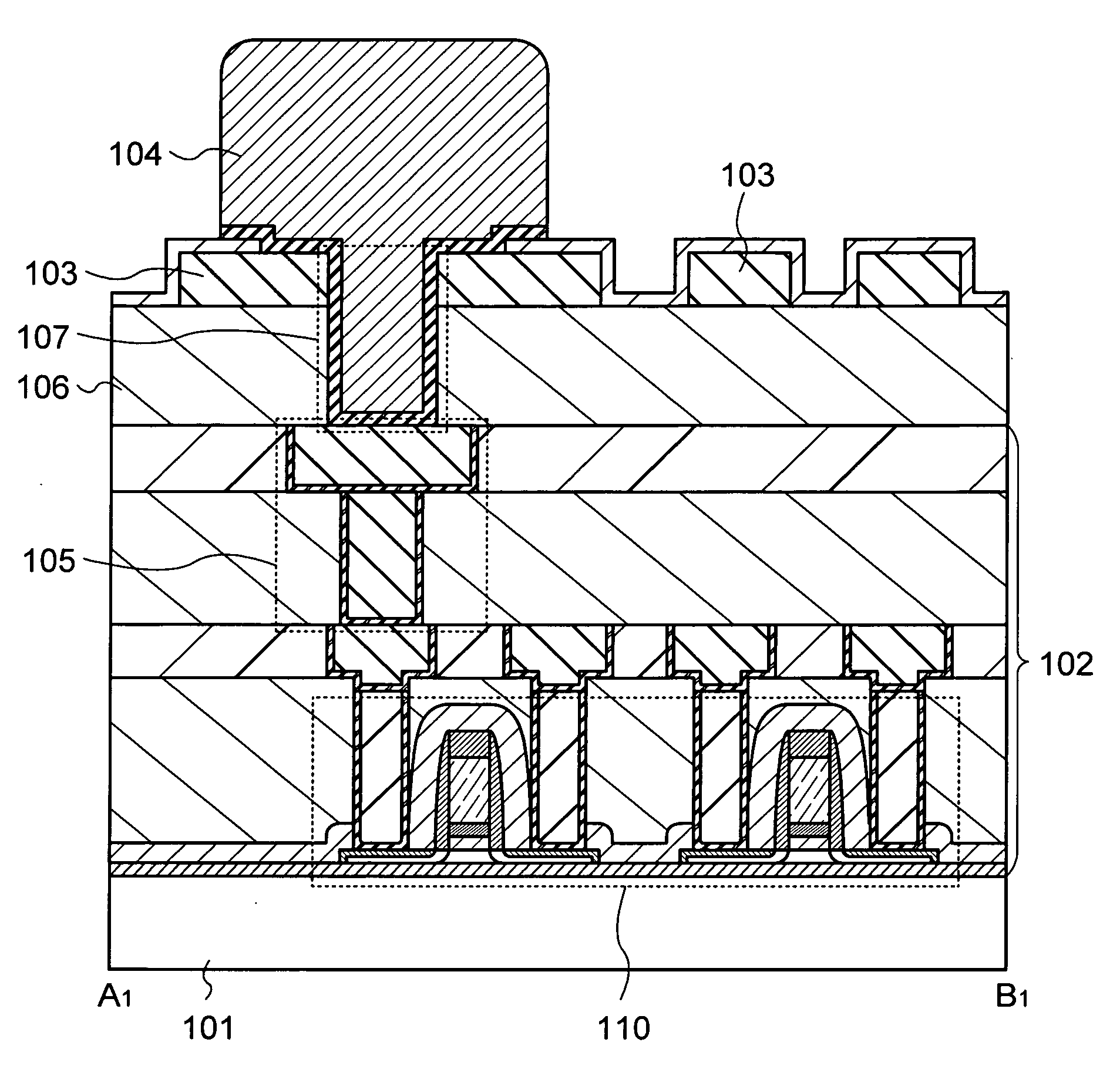
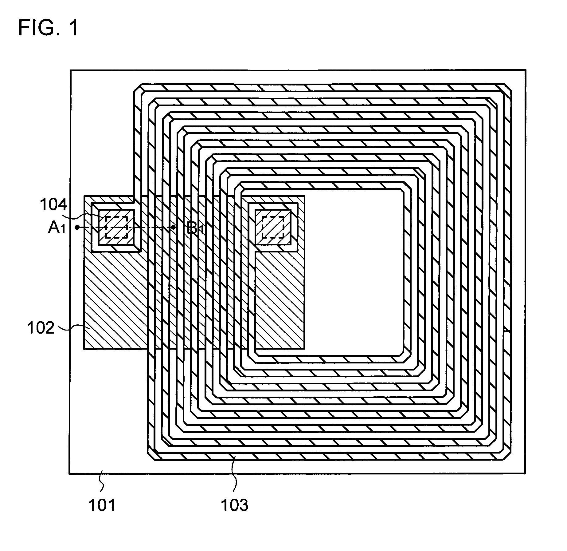
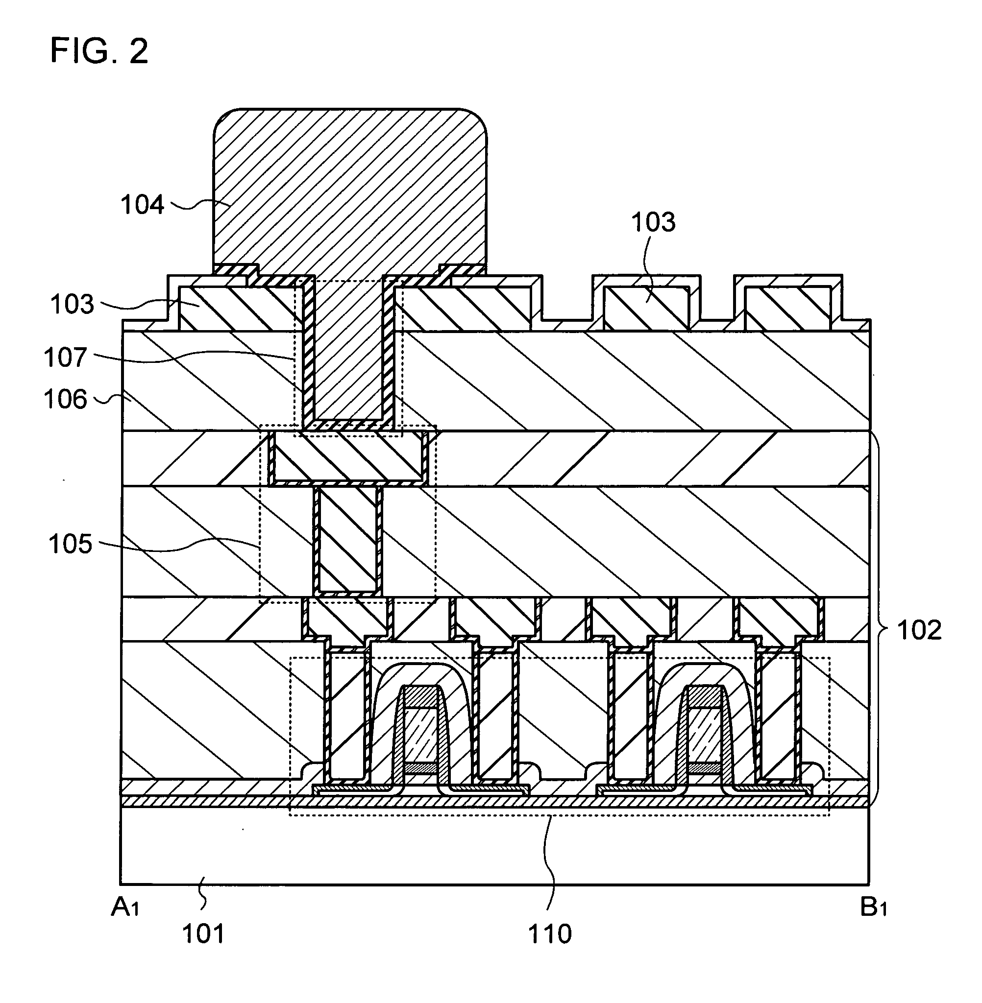
[0035]This embodiment mode describes an example of a semiconductor device of the present invention with reference to the drawings. In the description below, FIG. 1 shows a top surface of a semiconductor device and FIG. 2 is a cross-sectional view taken along line A1-B1 of FIG. 1.
[0036]A semiconductor device described in this embodiment mode includes an integrated circuit portion 102 which is provided over a substrate 101, a conductive film 103 serving as an antenna, and a conductive film 104 which electrically connects the integrated circuit portion 102 and the conductive film 103 (see FIGS. 1 and 2).
[0037]The conductive film 103 serving as an antenna is provided above the integrated circuit portion 102 with an insulating film 106 interposed therebetween, and the integrated circuit portion 102 and the conductive film 103 can partly or entirely overlap with each other. The integrated circuit portion 102 and the conductive film 103 serving as an antenna are electrically connected to e...
embodiment mode 2
[0063]This embodiment mode describes a semiconductor device having a structure different from that described in the above embodiment mode, with reference to the drawings.
[0064]A semiconductor device described in this embodiment mode includes an integrated circuit portion 102 which is provided over a substrate 101, a plurality of conductive films 103 serving as an antenna, and a conductive film 104 which electrically connects the integrated circuit portion 102 and the conductive film 103 (see FIG. 8). The plurality of conductive films 103 serving as an antenna is stacked over each other with an insulating film 121 alternately interposed therebetween, and each of the plurality of conductive films 103 is electrically connected to the conductive film 104. That is, the structure shown in FIG. 8 is different from that shown in FIG. 2 in that the plurality of conductive films 103 is provided to have a stacked structure.
[0065]The insulating film 121 is formed in a single layer or stacked la...
embodiment mode 3
[0073]This embodiment mode describes an example of a method for manufacturing the semiconductor device described in the above embodiment mode, with reference to the drawings. This embodiment mode describes the case where an element and the like included in an integrated circuit portion of a semiconductor device are provided using thin film transistors over one substrate. Further, this embodiment mode describes the case where after an element such as a thin film transistor is provided over a supporting substrate, the element is transferred to a flexible substrate so that a semiconductor device is manufactured. Furthermore, this embodiment mode describes the case where a plurality of integrated circuit portions and antennas is formed over one substrate (here, longitudinal 4×lateral 3) so that a plurality of semiconductor devices is manufactured. In the description below, FIGS. 12A to 13C are schematic top views and FIGS. 14A to 18B are schematic cross-sectional views taken along line ...
PUM
 Abstract
Description
Claims
Application Information
 - R&D
- Intellectual Property
- Life Sciences
- Materials
- Tech Scout
- Unparalleled Data Quality
- Higher Quality Content
- 60% Fewer Hallucinations
Browse by: Latest US Patents, China's latest patents, Technical Efficacy Thesaurus, Application Domain, Technology Topic, Popular Technical Reports.
© 2025 PatSnap. All rights reserved.Legal|Privacy policy|Modern Slavery Act Transparency Statement|Sitemap|About US| Contact US: help@patsnap.com


