AC light emitting diode having full-wave light emitting cell and half-wave light emitting cell

a technology of light emitting diodes and ac leds, which is applied in the direction of discharge tubes luminescnet screens, process and machine control, instruments, etc., can solve the problems of easy damage, low efficiency, and low efficiency of leds, and achieve the effect of minimizing reverse voltage and increasing the effective light emitting area

Inactive Publication Date: 2013-01-15
SEOUL VIOSYS CO LTD
View PDF6 Cites 3 Cited by
  • Summary
  • Abstract
  • Description
  • Claims
  • Application Information

AI Technical Summary

Benefits of technology

[0012]Exemplary embodiments of the present invention provide an AC light emitting diode (LED) capable of minimizing reverse voltage applied to light emitting cells and increasing the effective light emitting area of the light emitting cells.
[0013]Exemplary embodiments of the present invention also provide an AC LED capable of improving the array structure of light emitting cells to minimize reverse voltage is applied to a single light emitting cell.

Problems solved by technology

Therefore, when the LED is directly connected to an AC power source, there is a problem in that the LED may not continuously emit light and may be easily damaged due to reverse current.
However, as the number of light emitting cells connected to the bridge rectifier is increased, high reverse voltage is applied to a specific light emitting cell in the bridge rectifier, and therefore, the light emitting cell in the bridge rectifier is damaged.
As a result, the LED may be damaged.
However, in this case, it is difficult to provide an LED operating under high-voltage AC power.
However, the use efficiency of light emitting cells is accordingly lowered.

Method used


Image

  • AC light emitting diode having full-wave light emitting cell and half-wave light emitting cell
  • AC light emitting diode having full-wave light emitting cell and half-wave light emitting cell
  • AC light emitting diode having full-wave light emitting cell and half-wave light emitting cell

Examples


Embodiment Construction

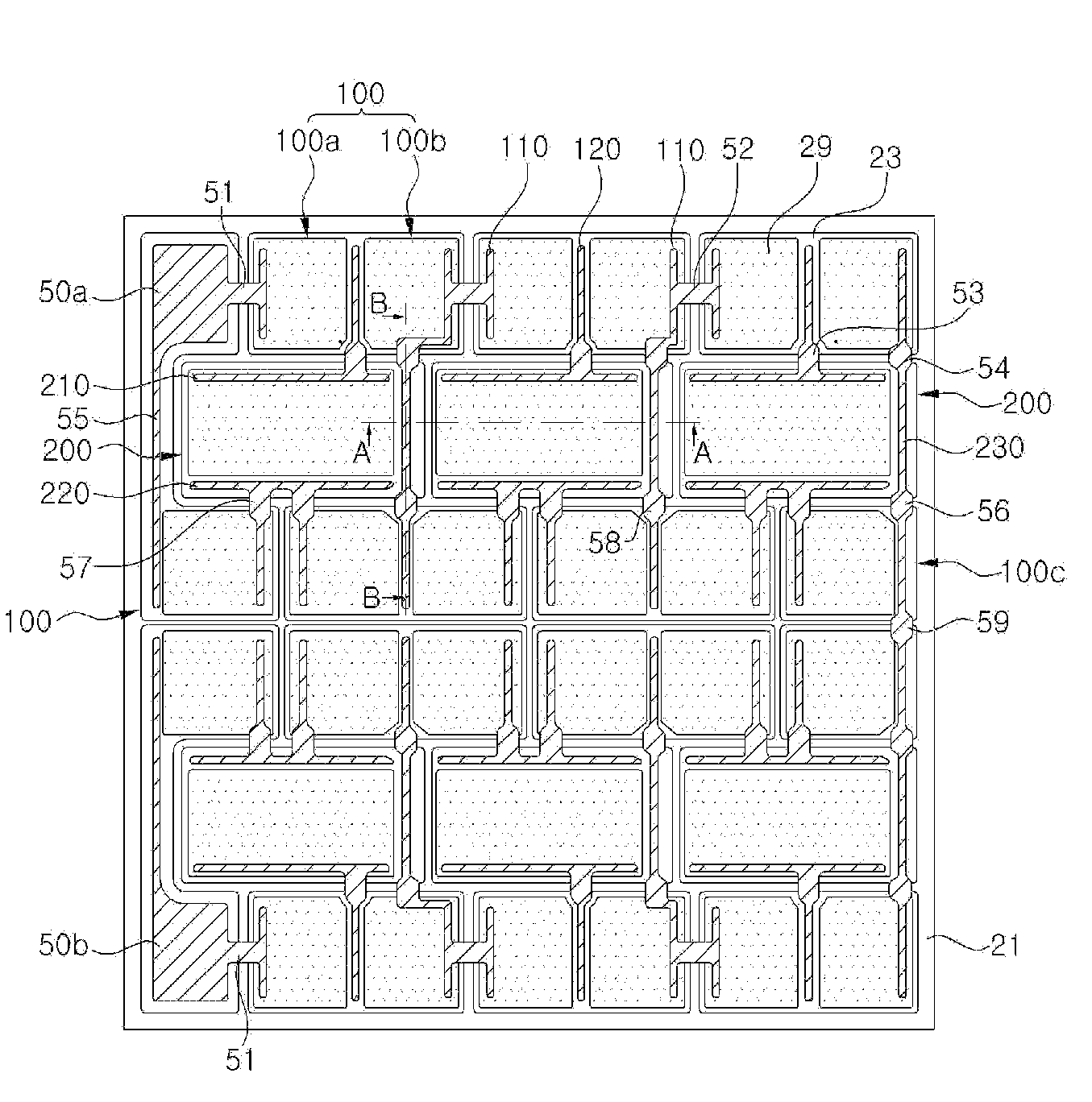
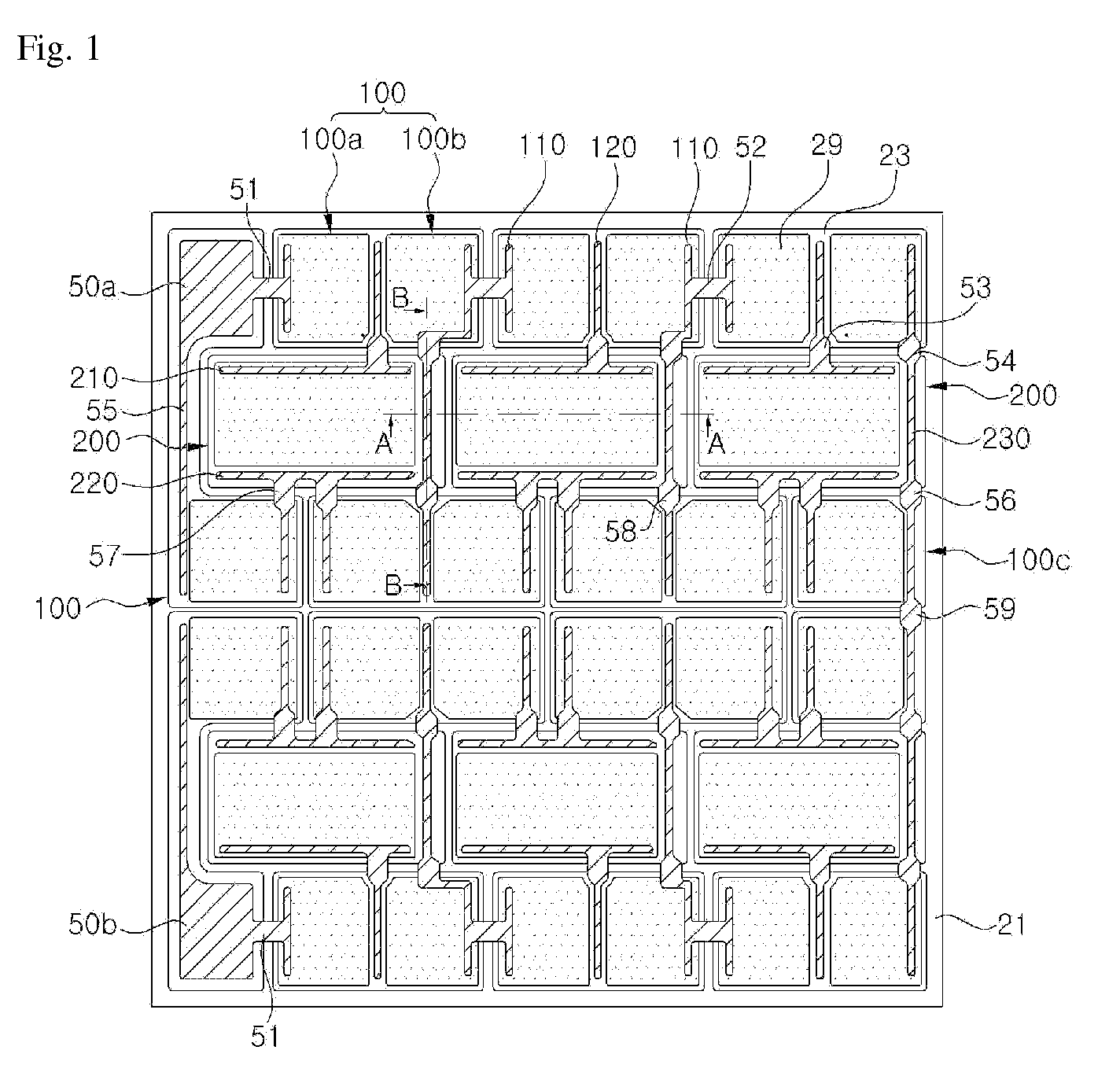
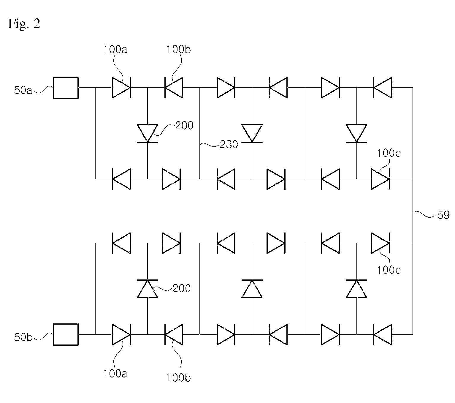
[0043]The invention is described more fully hereinafter with reference to the is accompanying drawings, in which embodiments of the invention are shown. This invention may, however, be embodied in many different forms and should not be construed as limited to the embodiments set forth herein. Rather, these embodiments are provided so that this disclosure is thorough, and will fully convey the scope of the invention to those skilled in the art. In the drawings, the size and relative sizes of layers and regions may be exaggerated for clarity Like reference numerals in the drawings denote like elements.

[0044]It will be understood that when an element or layer is referred to as being “on” or “connected to” another element or layer, it can be directly on or directly connected to the other element or layer, or intervening elements or layers may be present. In contrast, when an element is referred to as being “directly on” or “directly connected to” another element or layer, there are no i...


PUM


Abstract

The present invention discloses an alternating current (AC) light emitting diode (LED) having half-wave light emitting cells and full-wave light emitting cells. The AC LED has a plurality of light emitting cells electrically connected between bonding pads on a single substrate. The AC LED includes a first row of half-wave light emitting cells each having an anode terminal and a cathode terminal, a second row of full-wave light emitting cells each having an anode terminal and a cathode terminal, and a third row of half-wave light emitting cells each having an anode terminal and a cathode terminal. In the AC LED, the second row is arranged between the first row and the third row, and the third row includes a pair of light emitting cells that share a cathode terminal with each other. The cathode terminal shared by the pair of light emitting cells in the third row is electrically connected to the anode terminal of a corresponding light emitting cell of the half-wave light emitting cells in the first row through a conductor that is electrically insulated from the full-wave light emitting cells in the second row.

Description

CROSS-REFERENCE TO RELATED APPLICATIONS[0001]This application claims priority from and the benefit of Korean Patent Application No. 2009-0086877, filed on Sep. 15, 2009, and Korean Patent Application No. 2009-0090994, filed on Sep. 25, 2009, which are hereby incorporated by reference for all purposes as if fully set forth herein.BACKGROUND OF THE INVENTION[0002]1. Field of the Invention[0003]The present invention relates to a compound semiconductor light emitting diode (LED), and more particularly, to an alternating current (AC) LED having full-wave light emitting cells and half-wave light emitting cells.[0004]2. Discussion of the Background[0005]Compound semiconductor light emitting diodes (LEDS), e.g., GaN-based LEDS, are widely used for display elements and backlights. Further, these LEDs have less electric power consumption and a longer lifespan as compared with conventional light bulbs or fluorescent lamps, so that their application area has been expanded for general illuminati...

Claims


Application Information

Patent Timeline
Patent Type & Authority Patents(United States)
IPC IPC(8): H01L33/00
CPCH01L27/156H01L33/62H01L2924/0002H01L2924/00
Inventor KAL, DAE SUNGSEO, WON CHEOLLEE, JANG WOOSHIN, JIN CHEOLKIM, JONG KYUJIN, SANG KILEE, SO RA
Owner SEOUL VIOSYS CO LTD
Why Eureka
Try Eureka