
Stacker, stacking system or assembly and method for stacking

a stacking system and stacking technology, applied in the field of stacking, can solve the problems of high manufacturing cost of compensating stackers, slow drivers, and high design costs of servo-controlled or vector-controlled motors, and achieve the effects of increasing the speed of stacking, and increasing the height of the stacking

Inactive Publication Date: 2013-01-22
GAMMTECH CORP
View PDF29 Cites 15 Cited by
  • Summary
  • Abstract
  • Description
  • Claims
  • Application Information

AI Technical Summary

Benefits of technology

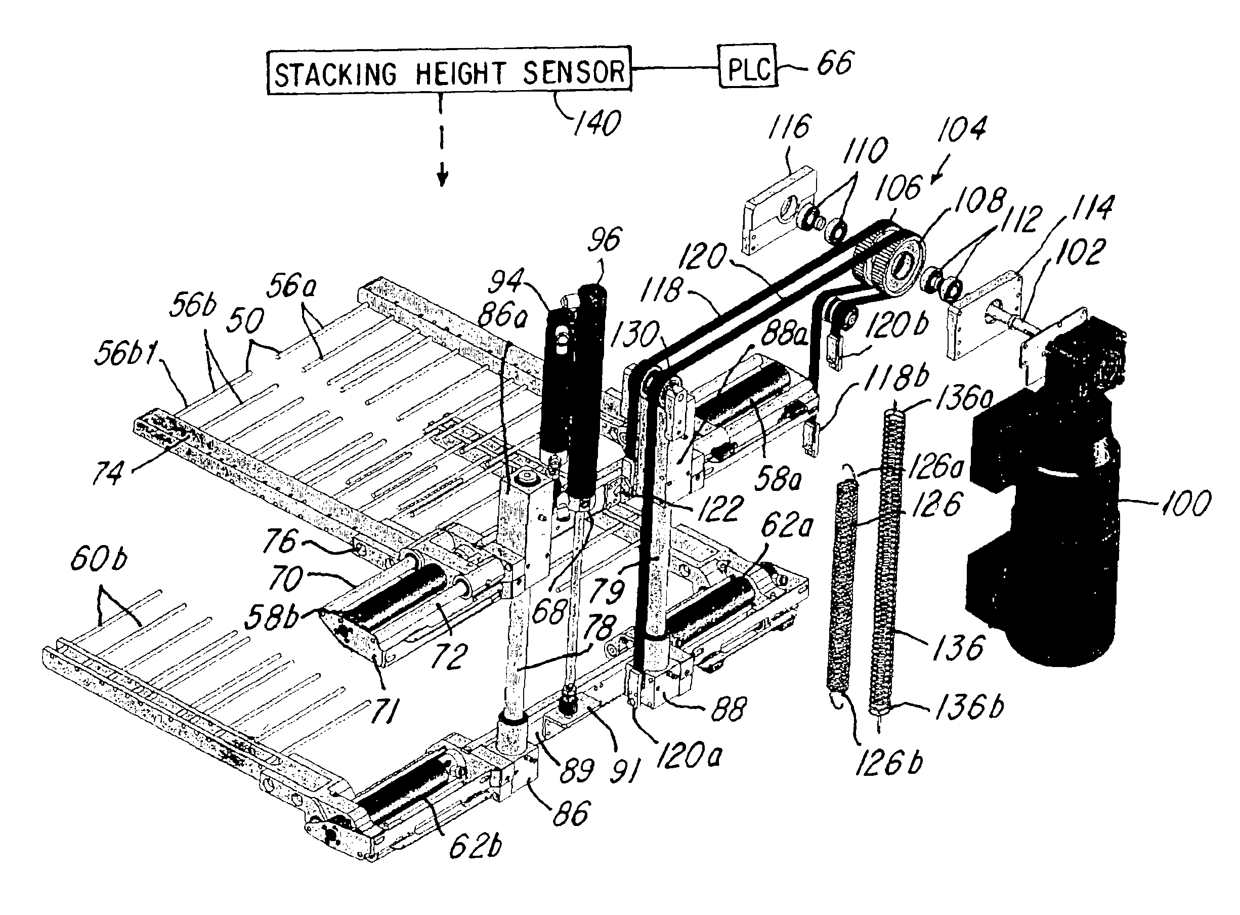
The invention provides a device control system that allows for the use of actuators or cylinders to move product supports in combination with a driver that can accurately index the product supports at a constant speed in a downward direction to maintain a constant drop height. The system also allows for the use of faster speeds for raising printed material supports.

Problems solved by technology

The servo-controlled or vector-controlled motor designs are expensive components and contribute to high manufacturing costs of the compensating stacker.
These types of drivers are also slow and their machine failure recovery (i.e., the recovery time needed to move the grid units from a lower release position where the printed materials are released to the rotary table to an upper stacking position where they can begin receiving printed materials for stacking) is slow because the units were moved back into their home positions with the servo-motor for positioning referencing.
These motors, while being accurate, are more expensive and difficult to maintain than other types of drivers, such as actuators or pneumatic cylinders.
However, the other types of drivers are not as accurate and cannot be used where accurate control and speed are needed.
Unfortunately, these other types of drivers, such as pneumatic actuators, do not accurately index at slow speeds which are required of conventional stackers which need to maintain a constant drop height and rate during a stacking process.
One drawback of the prior art stackers mentioned is they commonly used two motors with drives and required a close coupled connection of each grid section with a motor.
This resulted in high costs because of the two motors, drives and the like.

Method used


Image

  • Stacker, stacking system or assembly and method for stacking
  • Stacker, stacking system or assembly and method for stacking
  • Stacker, stacking system or assembly and method for stacking

Examples


Embodiment Construction

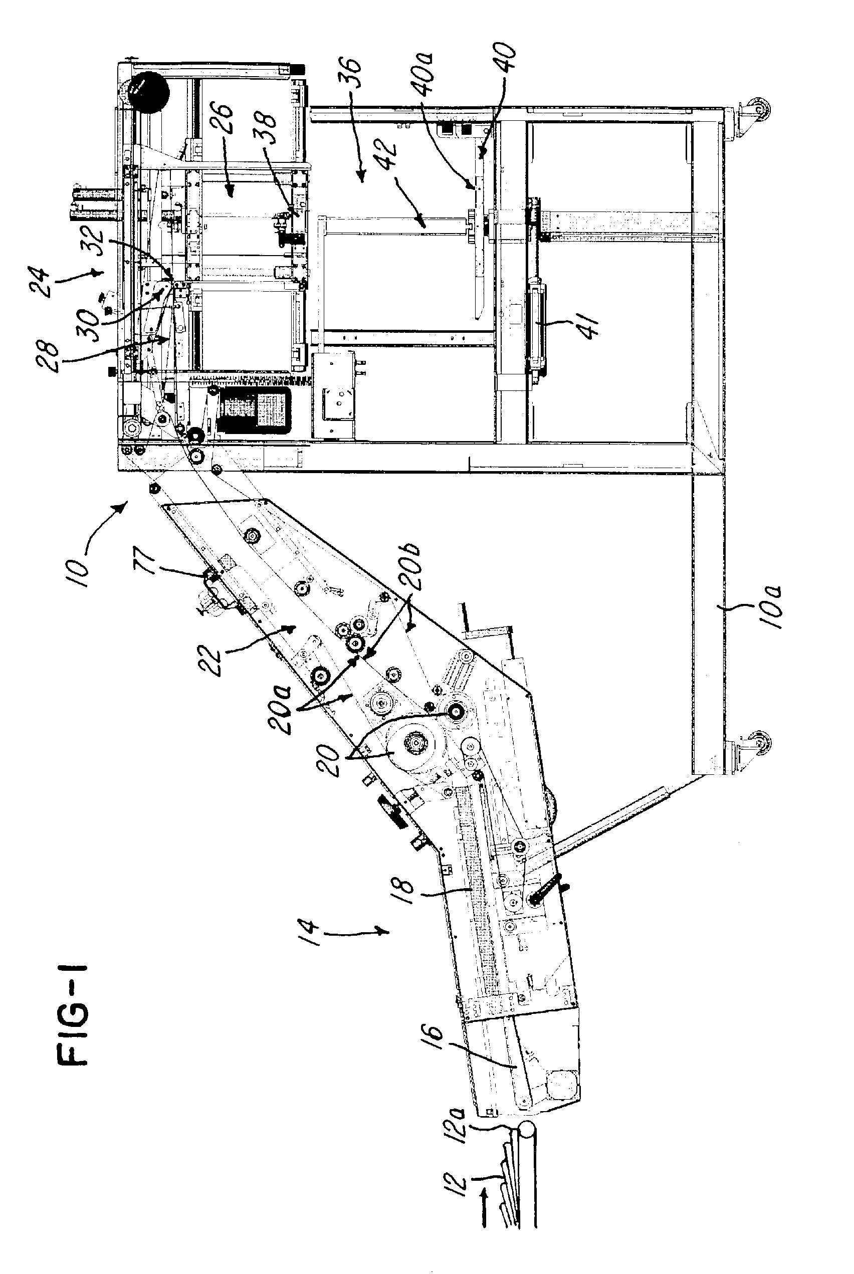
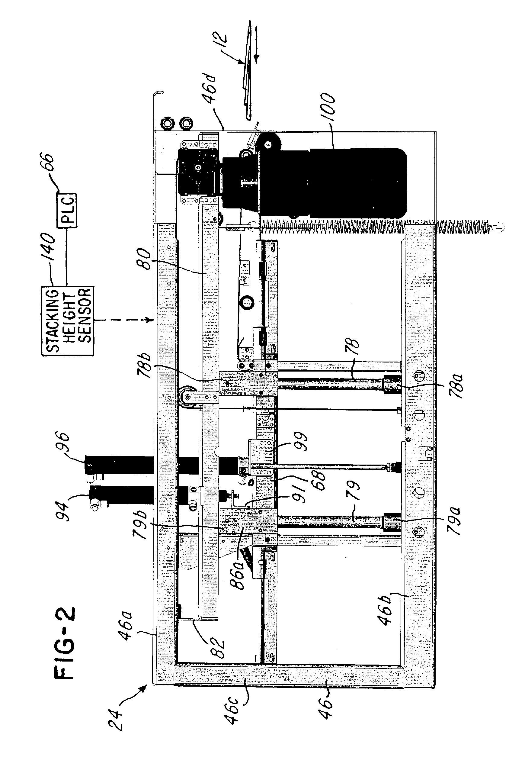
[0028]Referring now to FIGS. 1-10, a stacking system or stacker 10 and method are shown for stacking a plurality of printed materials 12, such as printed materials that are received from a printing press (not shown). In the illustration being described, the printed materials 12FIG. 1) are provided to the stacker 10 in a shingled manner as shown.

[0029]The stacker 10 comprises a frame 10a onto which components are coupled to or mounted. The stacker 10 comprises a conventional feeding unit 14. The feeding unit 14 comprises a gate 16, a side jogger 18 for alignment and a crusher / pressing unit 20 for flattening the folded edges 12a of the printed materials 12 and delivering them to a stacking area 26 of the stacker 10. The feeding unit 14 comprises an inclined section 22 for feeding the plurality of printed materials 12 to a stacking unit or assembly 24 that is mounted to a frame 10a of the stacker 10. Note that the crusher / pressing unit 20 and the inclined section 22 comprise a pluralit...


PUM

PropertyMeasurementUnit
speedaaaaaaaaaa
heightaaaaaaaaaa
stacking heightaaaaaaaaaa

Abstract

A stacking system and method that utilizes a device control for precisely controlling the downward movement of at least one printed material support at a first speed, while substantially simultaneously permitting upward movement of the at least one support at a second speed which is greater than the first speed.

Description

BACKGROUND OF THE INVENTION[0001]1. Field of the Invention[0002]A stacker system, assembly and method for stacking printed materials, and more particularly, a stacking system, assembly and method that utilizes a drive control that permits driving at least one or a plurality of stacking supports at a precisely controlled first speed in a downward or descending direction and that permits free relatively uncontrolled movement in an ascending or upward direction.[0003]2. Description of the Related Art[0004]In the past, printing presses or other feeders would deliver printed materials in a shingled manner to a stacker that would stack the printed materials. The printed materials or products were, for example, journals, advertising brochures, newspapers, magazines and the like. The products were stacked in a stack, which contained sub-stacks that were displaced by 180°. The printed products usually had a fold, so a stacking of the printed products with a displacement of 180° was required ...

Claims


Application Information

Patent Timeline
Patent Type & Authority Patents(United States)
IPC IPC(8): B65H29/16B65H29/18B65H31/32
CPCB65G57/11B65H31/18B65H31/32B65G57/00B65G57/06B65H2301/42112B65H2301/422615B65H2301/4451B65H2403/72B65H2511/152B65H2511/30B65H2513/10B65H2701/1932B65H2220/09B65H2220/01B65H2220/02B65H31/3018B65H2511/15
Inventor GAMMERLER, GUNTER
Owner GAMMTECH CORP
Learn More