Method and apparatus for representing 3D image records in 2D images

a technology of image data and 2d images, applied in the field of two-dimensional image representation of three-dimensional (3d) image data sets, can solve the problems of difficult to understand global positioning, difficult to represent these three-dimensional (3d) data, and irritating, so as to improve the depth of 2d images

Active Publication Date: 2013-01-22
TOMTEC IMAGING SYST
View PDF12 Cites 5 Cited by
  • Summary
  • Abstract
  • Description
  • Claims
  • Application Information

AI Technical Summary

Benefits of technology

[0015]The present invention to provides a new method and an apparatus therefor, which improves the sense of depth of 2D images generated from 3D image data sets.
[0038]However, a variant is preferred in which the starting and ending planes are tangential planes of a sphere, which encloses the entire 3D image data set in any viewing direction. This provides the advantage that the distance between starting and ending planes is constant from any viewing direction, and therefore the depth effect does not change according to the different viewing directions.

Problems solved by technology

This results in the problem how to represent these three-dimensional (3D) data, as typical display devices such as a screen and a printer provide two-dimensional (2D) image planes only.
Especially when representing volume records of complicated anatomic regions (for example 3D / 4D ultrasonic images), it is often difficult to understand the global positioning.
If, for example, a color chart already containing a blue gradient was used for generating the picture, a background change to blue is not very efficient and rather irritating.
However, this is not applicable particularly for anatomic data, because these images are often not clearly arranged and the observer is not able to distinguish between perspective foreshortening and atrophy of the organ observed.
The methods for depth cueing have also major disadvantages: fogging makes the image unclear in greater depth, the contours become blurred “grey-in-grey”, and the sense of depth is accompanied by a loss of information.
In summary, the methods of depth cueing have great disadvantages particularly in the field of representation of medical 3D or 4D image data sets.
Therefore, the global relations (relative orientation, distance, position, etc.) of the different structures in an anatomic image data set cannot be recognized easily in many cases.

Method used


Image

  • Method and apparatus for representing 3D image records in 2D images
  • Method and apparatus for representing 3D image records in 2D images
  • Method and apparatus for representing 3D image records in 2D images

Examples


Embodiment Construction

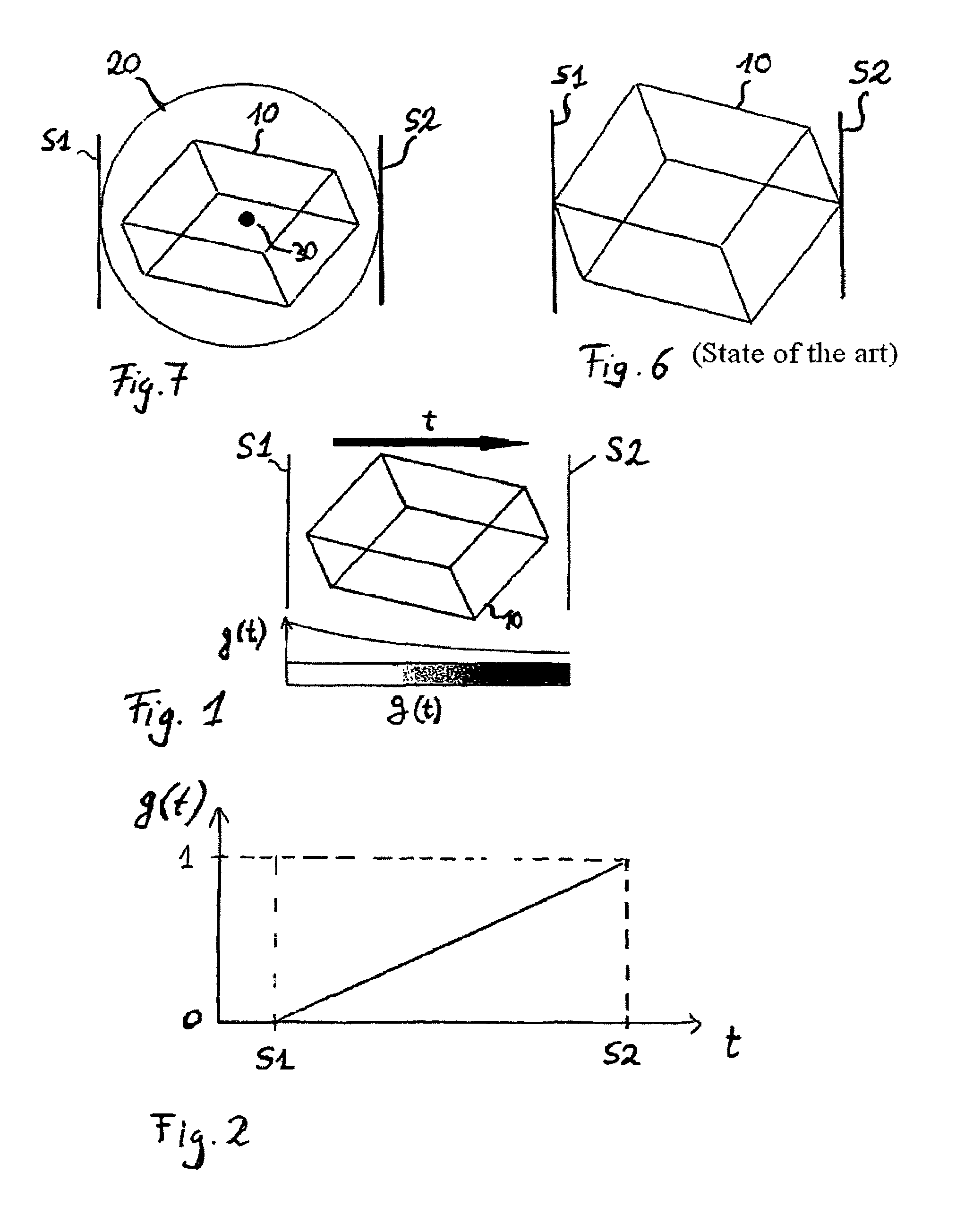
[0060]FIG. 1 demonstrates the principles of depth cueing: A 3D image volume is rendered in a viewing direction t. For the representation of depth effects, a weighting function g(t) is used which, in this example, decreases exponentially. Furthermore, a starting plane S1 and an ending plane S2 are defined, which enclose the 3D image volume 10 and thus define the region where the impression of depth shall be generated. According to another embodiment, the weighting function g(t) may increase linearly between the starting and ending planes S1 and S2, as is represented in FIG. 2. The type of weighting function determines whether the depth effects shall be clearly visible only in greater depth or whether depth effects shall be recognizable already in the foreground.

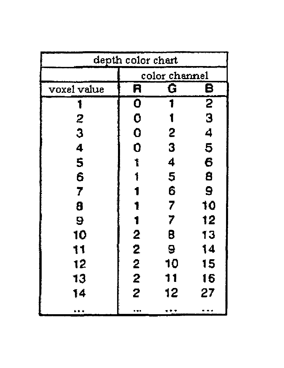
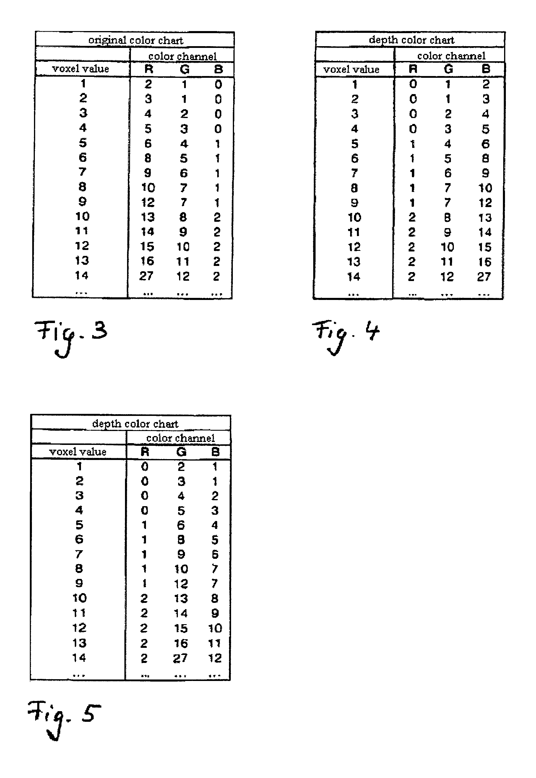
[0061]FIGS. 3 to 5 represent two examples of permuting an original color chart. FIG. 3 shows an exemplary original color chart which assigns a color value for each of the three color channels R, G and B to each voxel value hav...


PUM


Abstract

The invention relates to method and an apparatus for depth cueing, i.e. improving the sense of depth in two-dimensional images of three-dimensional volume data, said 2D images being generated using volume rendering. The invention is characterized in that a second depth color chart generated from the original color chart by permuting at least two color channels is used in the depth dimension. Alternatively, all three color channels can be permuted.

Description

FIELD OF THE INVENTION[0001]The invention relates to the field of representing three-dimensional (3D) image data sets in two-dimensional (2D) images, and particularly to a method and the apparatus therefor.BACKGROUND OF THE INVENTION[0002]Medical imaging methods, e.g. ultrasound (US), X-ray techniques, particularly Computed Tomography (CT), Magnetic Resonance Imaging (MRI), or nuclear medical imaging methods such as Positron Emission Tomography (PET) allow for achieving three-dimensional image data sets, also called volumetric data, of the body of human beings as well as animals. This results in the problem how to represent these three-dimensional (3D) data, as typical display devices such as a screen and a printer provide two-dimensional (2D) image planes only. One possibility for representing a three-dimensional (3D) data record is to put a sectional plane through the data record and to represent only those image elements (voxels) of the 3D image data set situated on this sectiona...

Claims


Application Information

Patent Timeline
Patent Type & Authority Patents(United States)
IPC IPC(8): G06T17/00G06T15/00
CPCG06T11/001G06T15/00
Inventor BRABEC, STEFAN
Owner TOMTEC IMAGING SYST
Why Eureka
Try Eureka