Micro-electromechanical system based switching

a micro-electromechanical and switching device technology, applied in the direction of protective switches using micromechanics, relays, emergency protective circuit arrangements, etc., can solve the problems of undesirable transient overvoltage, inability to easily visualize contactors such as vacuum contactors, and large fault currents in power systems

Active Publication Date: 2013-01-22
GENERAL ELECTRIC CO
View PDF68 Cites 12 Cited by
  • Summary
  • Abstract
  • Description
  • Claims
  • Application Information

AI Technical Summary

Problems solved by technology

However, fault currents in power systems are typically greater than the interrupting capacity of the electromechanical contactors.
Unfortunately, contactors such as vacuum contactors do not lend themselves to easy visual inspection as the contactor tips are encapsulated in a sealed, evacuated enclosure.
Further, while the vacuum contactors are well stated for handling the switching of large motors, transformers, and capacitors, they are known to cause undesirable transient overvoltages, particularly as the load is switched off.
Such zero crossing prediction is prone to error as many transients may occur in this prediction time interval.
However, because solid-state switches do not create a physical gap between contacts as they are switched into a non-conducing state, they experience leakage current.
Furthermore, due to internal resistances, if solid-state switches operate in a conducting state, they experience a voltage drop.
Both the voltage drop and leakage current contribute to the generation of excess heat under normal operating circumstances, which may affect switch performance and life.
Moreover, due at least in part to the inherent leakage current associated with solid-state switches, their use in circuit breaker applications is not practical.
Furthermore, switching currents on or off during current flow may produce arcs, or flashes of electricity, which are generally undesirable.
Therefore, direct current interruption imposes different switching requirements compared to alternating current interruption.
Electronic devices such as transistors or field-effect transistors may force DC current to lower levels, but have the drawback of having high conducting voltage drop and power losses.

Method used


Image

  • Micro-electromechanical system based switching
  • Micro-electromechanical system based switching
  • Micro-electromechanical system based switching

Examples


Embodiment Construction

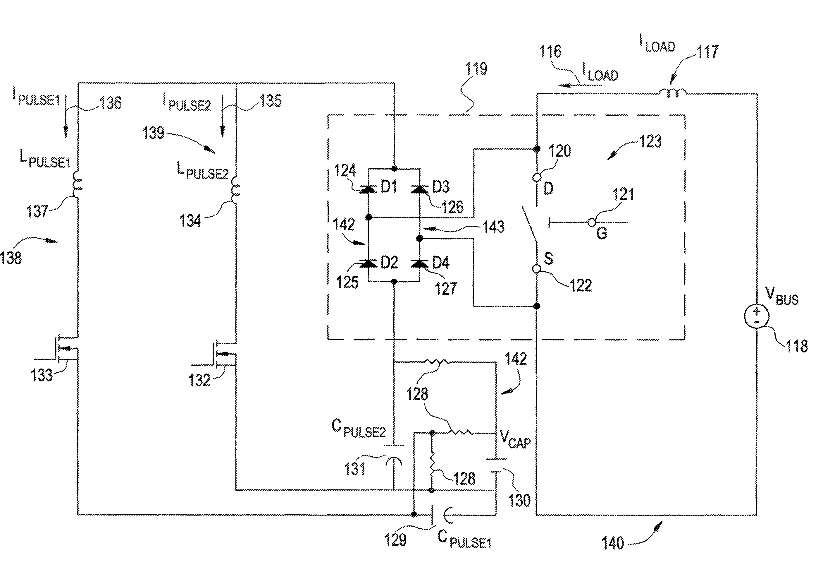
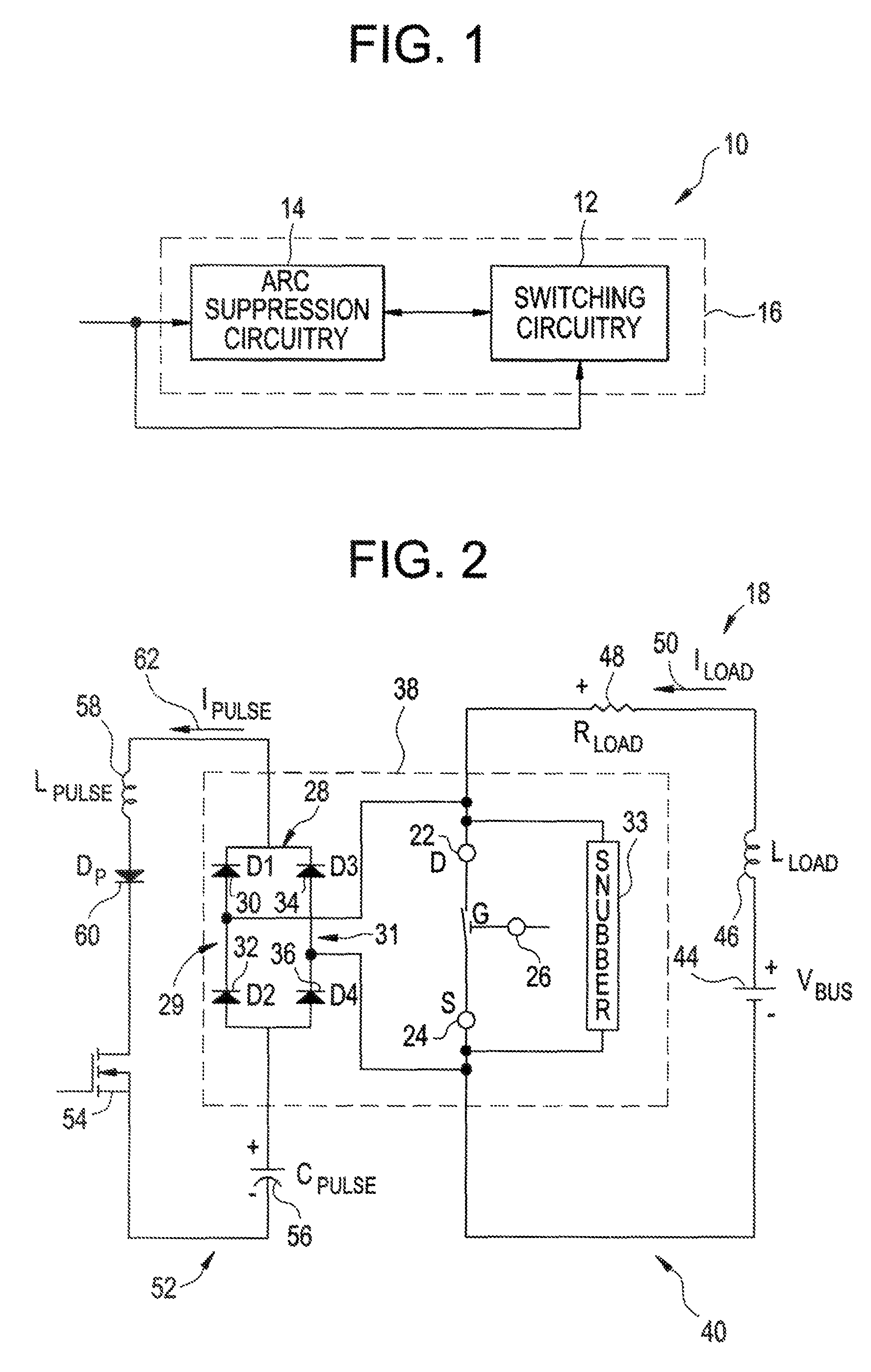
[0023]An embodiment of the invention provides an electrical interruption device suitable for arcless interruption of direct current. The interruption device includes micro electromechanical system (MEMS) switches. Use of MEMS switches provide fast response time. A Hybrid Arcless Limiting Technology (HALT) circuit connected in parallel with the MEMS switches provides capability for the MEMS switches to be opened without arcing at any given time regardless of current or voltage. A Pulse-Assisted Turn On (PATO) circuit connected in parallel with the MEMS switches provides capability for the MEMS switches to be closed without arcing at any given time.

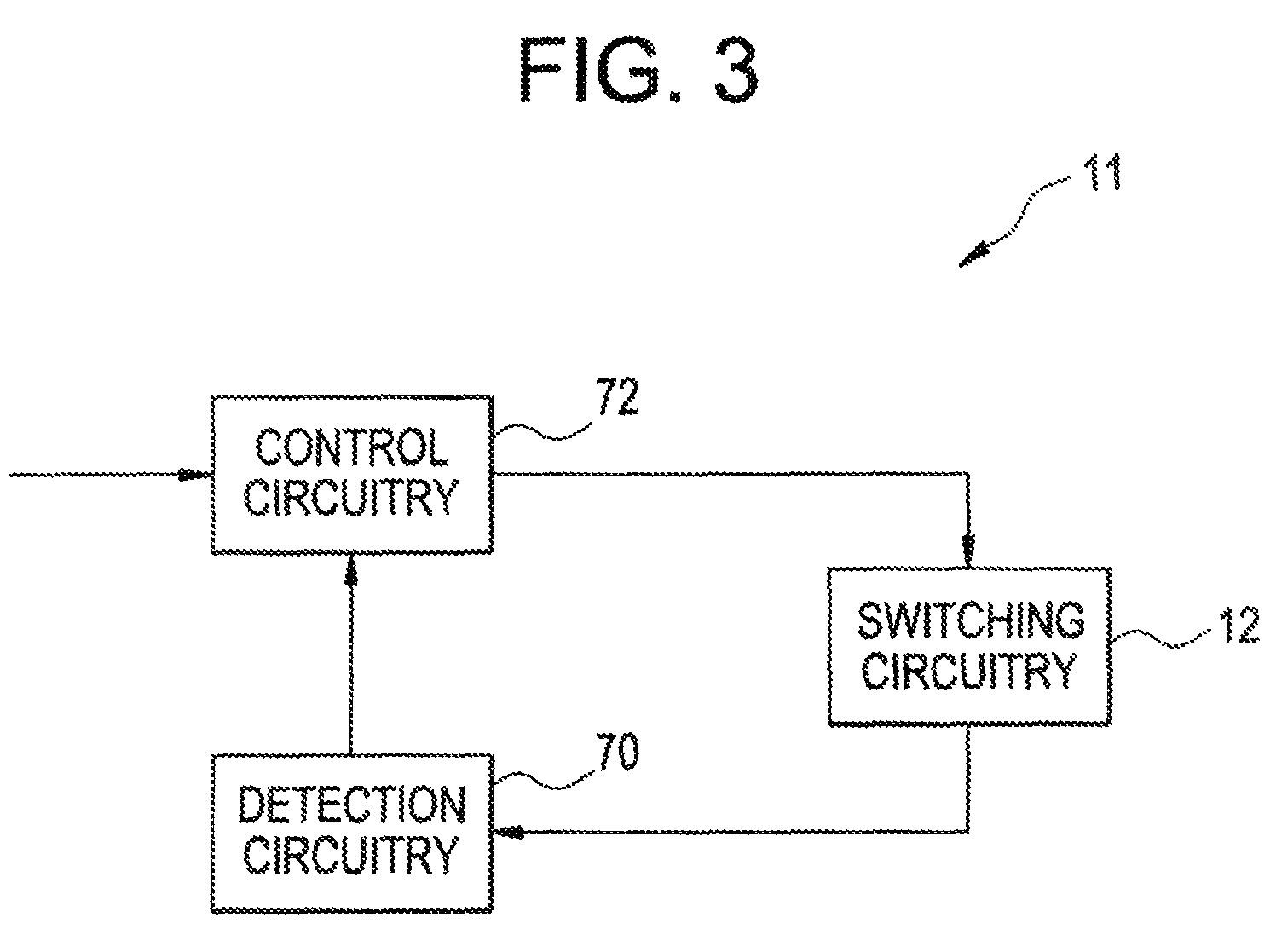
[0024]FIG. 1 illustrates a block diagram of an exemplary arcless micro-electromechanical system switch (MEMS) based switching system 10, in accordance with aspects of the present invention. Presently, MEMS generally refer to micron-scale structures that for example can integrate a multiplicity of functionally distinct elements, for example,...


PUM


Abstract

A current control device is disclosed. The current control device includes control circuitry integrally arranged with a current path and at least one micro electromechanical system (MEMS) switch disposed in the current path. The current control device further includes a hybrid arcless limiting technology (HALT) circuit connected in parallel with the at least one MEMS switch facilitating arcless opening of the at least one MEMS switch, and a pulse assisted turn on (PATO) circuit connected in parallel with the at least one MEMS switch facilitating arcless closing of the at least one MEMS switch.

Description

BACKGROUND OF THE INVENTION[0001]Embodiments of the invention relate generally to switching devices for switching on / off a current in current paths, and more particularly to micro-electromechanical system based switching devices.[0002]To switch on / off current in electrical systems, a set of contacts may be used. The contacts may be positioned as open to stop current, and closed to promote current flow. Generally, the set of contacts may be used in contactors, circuit-breakers, current interrupters, motor starters, or similar devices. However, the principles of switching current on / off may be understood through explanation of a contactor.[0003]A contactor is an electrical device designed to switch an electrical load ON and OFF on command. Traditionally, electromechanical contactors are employed in control gear, where the electromechanical contactors are capable of handling switching currents up to their interrupting capacity. Electromechanical contactors may also find application in ...

Claims


Application Information

Patent Timeline
Patent Type & Authority Patents(United States)
IPC IPC(8): H02H3/02
CPCH01H59/0009H01H9/30H01H9/542H01H2071/008
Inventor PREMERLANI, WILLIAM JAMESSUBRAMANIAN, KANAKASABAPATHIKEIMEL, CHRISTOPHER FREDO'BRIEN, KATHLEEN ANNPARK, JOHN NORTON
Owner GENERAL ELECTRIC CO
Why Eureka
Try Eureka