Method and apparatus for two-dimensional finger motion tracking and control

a two-dimensional finger and motion tracking technology, applied in the field of two-dimensional finger motion tracking and control, to achieve the effects of improving fingerprint imagers, enhancing accuracy, and enhancing robustness and accuracy

Active Publication Date: 2013-01-22
SYNAPTICS INC
View PDF390 Cites 68 Cited by
  • Summary
  • Abstract
  • Description
  • Claims
  • Application Information

AI Technical Summary

Benefits of technology

[0028]Further improvements in the finger location and movement sensing technology previously disclosed in U.S. Pat. Nos. 7,099,496 and 7,146,024, and also Publication Nos. US 20050244038 and US 20050244039 that are commonly assigned to applicant and incorporated herein by reference, are possible, and some of these additional improvements are described herein. In particular, the present invention teaches improved signal analysis techniques that can enable finger locations and movement during a finger swipe for a fingerprint scan to be determined with improved accuracy and precision, greater resistance to noise (false signals), and over a wider variety of different finger swipe techniques. The present invention also teaches techniques to use this improved information to produce more accurate fingerprint images.
[0030]These enhanced accuracy finger position and motion sensors can be used in a greater variety of different applications. In one type of application, these higher accuracy finger motion sensors can be used in conjunction with partial fingerprint scanners to produce improved fingerprint imagers that function with greater robustness and accuracy. In a second type of application, these higher accuracy finger motion sensors may be used (either with or without a partial fingerprint imager) to control electronic devices. When several of these finger motion and position sensors are aligned in different directions, finger motion over a two dimensional surface may be detected. This allows a new type of finger controlled “mouse” computer input device to be created. Motion of a finger along the surface of such sensors may allow a user to control the movement of an indicator on a display screen, and control a microprocessor device. Such techniques are particularly useful for small space constrained devices, such as cell phones, smart cards, music players, portable computers, personal digital accessories, and the like.

Problems solved by technology

The problem, however, is that the noisy area is both broad and poorly defined, and this leads to inaccurate results.

Method used


Image

  • Method and apparatus for two-dimensional finger motion tracking and control
  • Method and apparatus for two-dimensional finger motion tracking and control
  • Method and apparatus for two-dimensional finger motion tracking and control

Examples


Embodiment Construction

[0062]The techniques discussed here can generally be used with the sensing circuits previously described in U.S. Pat. Nos. 7,099,496 and 7,146,024, and also U.S. Publication Nos. US 2005-0244038A1 and US 2005-0244039A1 that are commonly assigned to applicant and incorporated herein by reference. Please see these applications for a more detailed discussion of the electronic elements. The present invention is focused on signal analysis techniques, methods, and algorithms, and improved fingerprint sensors and navigational devices that use these previously disclosed finger position sensing devices. Thus the present application will not reiterate the details of these previously discussed electrical circuits unless they are relevant to the present invention.

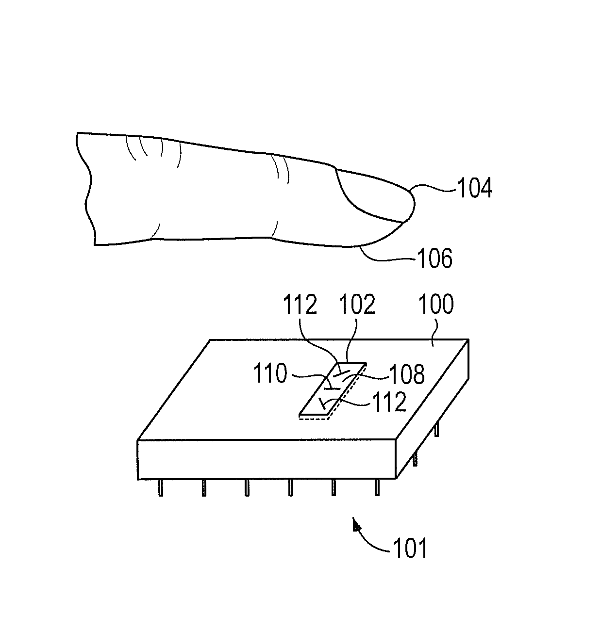
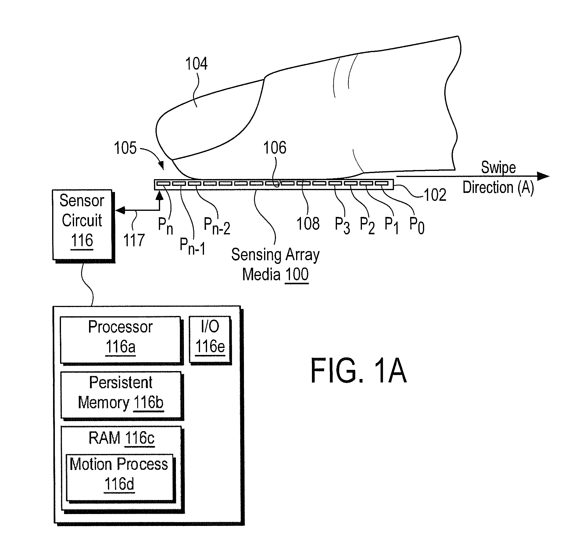
[0063]Referring to FIG. 1A, a side diagrammatic view of a finger position sensor in contact with a finger is illustrated according to the invention. The sensing array (sensing array medium) (100) is illustrated in somewhat of a side di...


PUM


Abstract

Enhanced accuracy finger position and motion sensors devices, algorithms, and methods are disclosed that can be used in a variety of different applications. The sensors can be used in conjunction with partial fingerprint imagers to produce improved fingerprint scanners. The finger motion sensors may also be used (either with or without a partial fingerprint imager) to control electronic devices. When several of these finger motion and position sensors are aligned in different directions, finger motion over a two dimensional surface may be detected. This creates a finger controlled “mouse” computer input device. Motion of a finger along the surface of such sensors may allow a user to control the movement of an indicator on a display screen, and control a microprocessor device. Such techniques are particularly useful for small space constrained devices, such as cell phones, smart cards, music players, portable computers, personal digital accessories, and the like.

Description

RELATED APPLICATIONS[0001]This application is related to U.S. Non-Provisional application Ser. No. TBD, filed Dec. 14, 2007, entitled “Method and Apparatus for Fingerprint Image Reconstruction,” and U.S. Non-Provisional application Ser. No. TBD, filed Dec. 14, 2007, entitled “Method and Algorithm for Accurate Finger Motion Tracking.”[0002]This application is a continuation in part of, and claims the priority benefit of, U.S. Non-Provisional application Ser. No. 11 / 519,383, filed Sep. 11, 2006, and also a continuation in part of U.S. Non-Provisional application Ser. No. 11 / 519,362, filed Sep. 11, 2006.[0003]This application is a continuation in part of, and claims the priority benefit of, U.S. Non-Provisional application Ser. No. 11 / 107,682, filed Apr. 15, 2005. U.S. Non-Provisional patent application Ser. No. 11 / 107,682 claimed the priority benefit of U.S. Provisional Patent Application No. 60 / 563,139, filed Apr. 16, 2004.[0004]This application is also a continuation in part of, and...

Claims


Application Information

Patent Timeline
Patent Type & Authority Patents(United States)
IPC IPC(8): G06K9/00
CPCG06K9/00026G06F2203/0338G06V40/1335
Inventor BENKLEY, FRED GEORGEGEOFFROY, DAVID JOSEPHSATYAN, PALLAVI
Owner SYNAPTICS INC
Why Eureka
Try Eureka