
Differential

a technology of differential gearings and gearings, applied in the field of differential gearings, can solve the problems of large space requirements, high weight, and disadvantages of prior art designs

Active Publication Date: 2013-01-29
NEUMAYER TEKFOR ENG GMBH
View PDF18 Cites 6 Cited by
  • Summary
  • Abstract
  • Description
  • Claims
  • Application Information

AI Technical Summary

Benefits of technology

The present invention is related to a differential gear assembly for a vehicle. The technical effects achieved include: a) the drive gear is designed in a way that it encloses at least one interior space, and the connector element (often a differential cage) is arranged inside the drive gear, which simplifies the assembly process and reduces manufacturing complexity of the differential; b) the drive gear provides an open interior space, which allows for easy oil sealing and filling without oil loss when disassembling the side shafts; c) the surface of the drive gear and compensating gear pin are designed for easy access for welding or laser welding; and d) a bowl sleeve prevents jamming of the axle gear and compensating gear, and thrust washers provide good glide conditions between the compensating gear and the associated backing positioned behind it. Additionally, the invention provides a simpler way of adjusting the contact pattern and ensures consistent performance regardless of varying loads.

Problems solved by technology

Disadvantages in the designs given by the prior art arise particularly from the differential cage.
The latter is commonly difficult to manufacture, leads to large space requirements, and involves high weight.

Method used


Image

  • Differential
  • Differential
  • Differential

Examples


Embodiment Construction

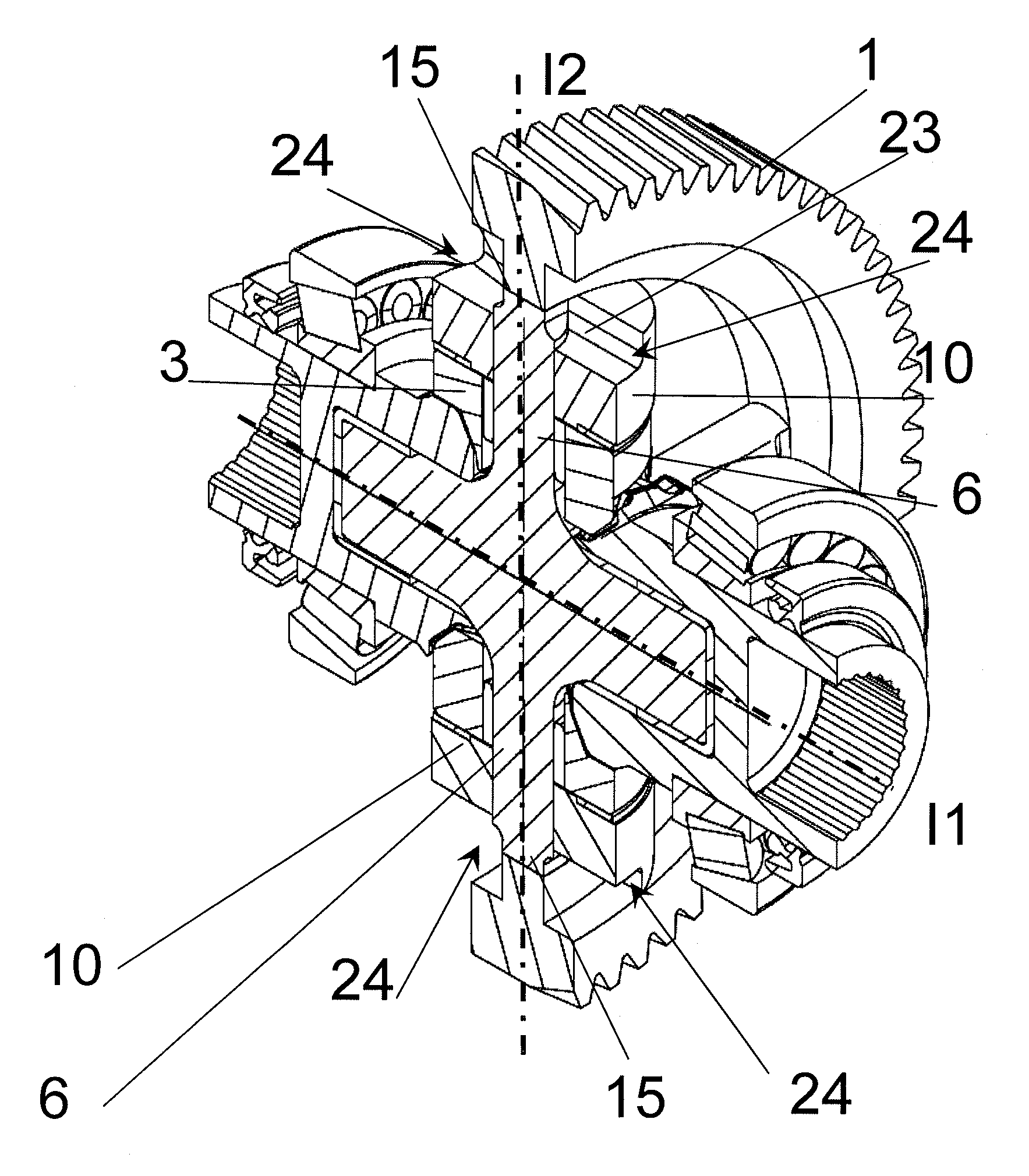
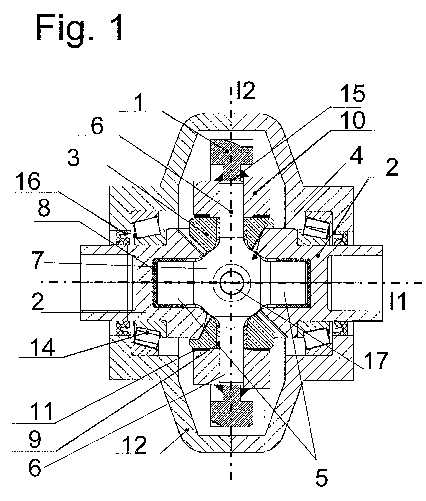
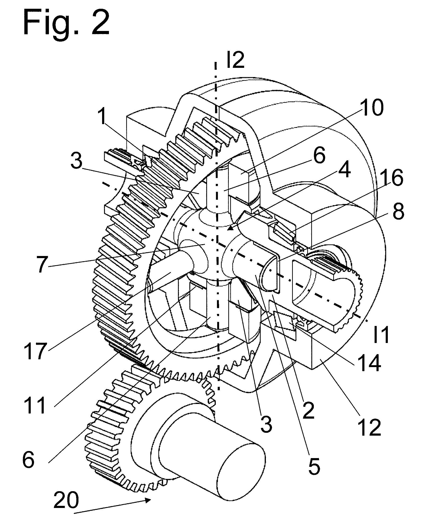
[0088]A first variant of the differential according to the invention is shown in the cutaway view in FIG. 1 as well as the associated spatial illustration in FIG. 2. The connector element 4 is arranged inside the housing 12, substantially in the center thereof, and is constructed as a differential cage in the prior art. In this embodiment, it has the shape of a substantially solid central region 7, wherein a total of six pins extend from the connector element 4 in this embodiment (see FIG. 2). In this case, these are two axle gear pins 5, two compensating gear pins 6, and two fastening pins 17. The pins 5, 6, 17 in this case are substantially cylindrical in design, wherein the diameter of the axle gear pins 5 in the embodiment shown here is larger than the other two types of pins 6, 17.

[0089]The connecting element 4, which is consequently star-shaped in this embodiment, and which can also be characterized as a planetary carrier in this functional context, is connected to the drive g...


PUM


Abstract

A differential, having at least one drive gear, at least two axle gears, at least one compensating gear, and at least one connector element, in which the connector element is subjected to at least one first torque from the drive gear and transmits at least one second torque to at least one of the at least two axle gears. The drive gear is constructed in such a manner that the drive gear at least partially encloses at least one interior space, and the connector element is arranged at least partially inside the interior space enclosed at least partially by the drive gear.

Description

CROSS REFERENCE TO RELATED APPLICATIONS[0001]This application is a continuation of international patent application no. PCT / DE2010 / 000938, filed Aug. 6, 2010 designating the United States of America and published in German on Mar. 10, 2011 as WO 2011 / 026454 A1, the entire disclosure of which is incorporated herein by reference. Priority is claimed based on Federal Republic of Germany patent application nos. DE 10 2009 039 753.1, filed Sep. 2, 2009, and DE 10 2009 055 867.5, filed Nov. 26, 2009, the entire disclosures of each of which are likewise incorporated herein by reference.BACKGROUND OF THE INVENTION[0002]The invention relates to a differential, having at least one drive gear, having at least two axle gears, having at least one compensating gear, and having at least one connector element, wherein the connector element receives at least one first torque from the drive gear, and wherein the connector element transmits at least one second torque to at least one of the at least tw...

Claims


Application Information

Patent Timeline
Patent Type & Authority Patents(United States)
IPC IPC(8): F16H48/06F16H48/10
CPCF16H48/08F16H48/10Y10T74/19088F16H2048/102F16H2048/385F16H2048/085
Inventor FINKENZELLER, EVA-MARIAKUEMPEL, RENALDFUCHS, KATHRIN
Owner NEUMAYER TEKFOR ENG GMBH
Learn More