
Tubular prosthesis

Active Publication Date: 2013-01-29
CORMOVE
View PDF19 Cites 59 Cited by
  • Summary
  • Abstract
  • Description
  • Claims
  • Application Information

AI Technical Summary

Benefits of technology

The invention is a tubular prosthesis that can be easily placed and can be reliably positioned.

Problems solved by technology

It is difficult to ensure that the prosthesis is held axially within the vessel, i.e. in the long direction of the vessel, and the prosthesis runs the risk of being moved along the vessel under drive from the flow of blood.
In addition, the prosthesis runs the risk of not being pressed exactly against the surface of the blood vessel, because of its irregular section.
Those fastener means are not very reliable and they are difficult to put into place.

Method used


Image

  • Tubular prosthesis
  • Tubular prosthesis
  • Tubular prosthesis

Examples


Embodiment Construction

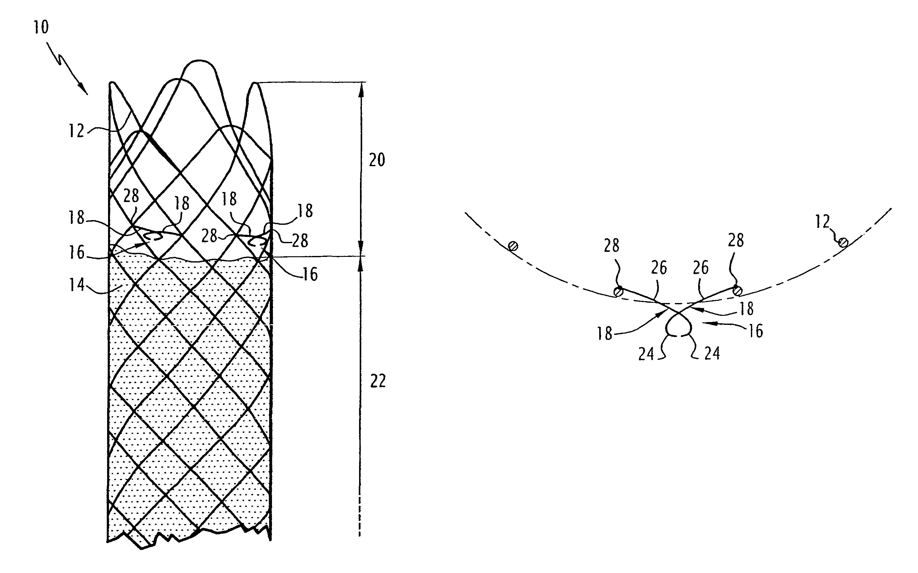
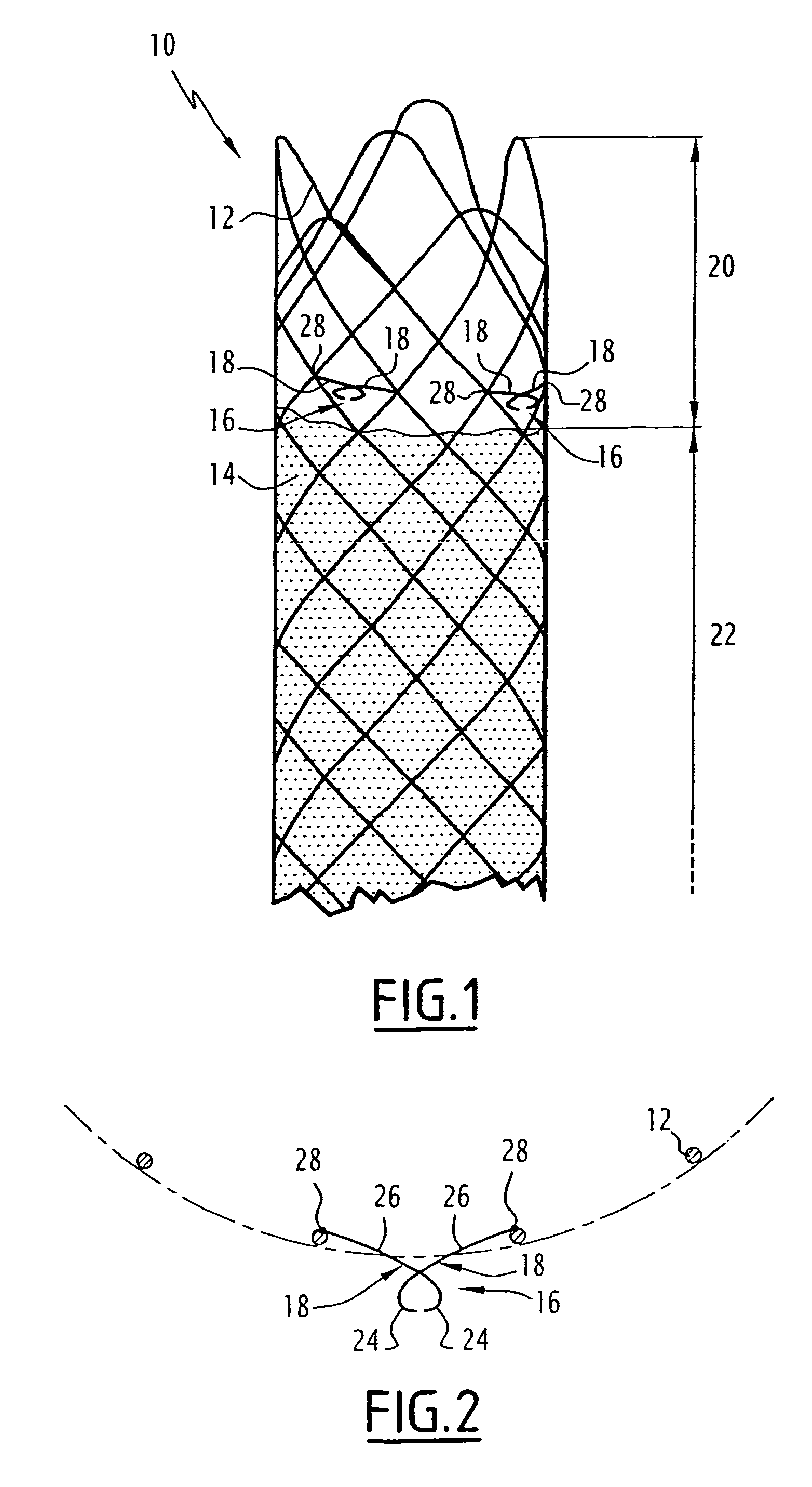
[0034]The tubular prosthesis 10 shown in FIG. 1 is to be put into place in a blood vessel. It comprises a tubular lattice 12 that is embedded in a film 14 over substantially the entire length of the prosthesis. In the vicinity of one of its ends, the prosthesis also comprises three clamps 16 that are angularly spaced apart regularly at (evenly around) its periphery.

[0035]Each clamp 16 is made up of two hooks 18 carried by the metal lattice 12. These hooks can be moved relative to each other between a spaced-apart position in which the clamp is open, and a close-together position in which the clamp is closed.

[0036]The clamps 16 are provided on an end segment 20 of the prosthesis that does not have any film 14, the lattice 12 thus not being covered in this region. In contrast, the main segment of the prosthesis, indicated by reference number 22, has the lattice 12 embedded in the film 14.

[0037]The lattice 12 is made of stainless steel of biocompatible quality. For example, it is made ...


PUM


Abstract

The radially deformable tubular prosthesis comprises a lattice that is deformable between a retracted state of small diameter and an expanded state of greater diameter. It includes at least two external hooks defining between them a clamp for hooking in external tissue, the two hooks being carried by the lattice and being movable between a spaced-apart position in which the clamp is open, and a closer-together position in which the clamp is closed.

Description

BACKGROUND OF THE INVENTION[0001]The present invention relates to a tubular prosthesis of the type that is radially deformable, comprising a lattice that is deformable between a retracted state of small diameter and an expanded state of larger diameter.[0002]For various types of treatment, it is known to place a tubular prosthesis inside a blood vessel, whether a vein or an artery. Such tubular prostheses are generally referred to by the term “stent”.[0003]The prosthesis is brought to the inside of the vessel while it is in its retracted state, and then for positioning purposes, the prosthesis is expanded so as to press against the inside surface of the vessel. This expansion is performed either automatically because of the elasticity of the prosthesis lattice, or else under drive from an internal balloon being inflated, leading to plastic deformation of the material constituting the lattice.[0004]It is difficult to ensure that the prosthesis is held axially within the vessel, i.e. ...

Claims


Application Information

Patent Timeline
IPC IPC(8): A61F2/06A61F2/07A61F2/848A61F2/90A61F2/95
CPCA61F2/07A61F2/90A61F2/95A61F2002/8486A61F2002/9511A61F2220/0016A61F2002/072A61F2230/0013A61F2230/0054A61F2220/0008A61F2/848
Inventor PEROUSE, ERIC
Owner CORMOVE
Features
  • Generate Ideas
  • Intellectual Property
  • Life Sciences
  • Materials
  • Tech Scout
  • Unparalleled Data Quality
  • Higher Quality Content
  • 60% Fewer Hallucinations
Learn More