
Method of dynamically allocating contacts of a subscriber chip in a mobile terminal, and corresponding subscriber chip card and mobile terminal

a subscriber chip and mobile terminal technology, applied in the field of mobile telephony, can solve the problems of not being adapted, consuming software and hardware resources, and not being able to adapt to multiplexing technology,

Inactive Publication Date: 2013-01-29
ST ERICSSON SA
View PDF26 Cites 15 Cited by
  • Summary
  • Abstract
  • Description
  • Claims
  • Application Information

AI Technical Summary

Benefits of technology

The present invention allows a mobile device to dynamically allocate the contacts of a subscriber smart card between different electronic modules. This allows the mobile device to use the capabilities of the smart card in a flexible manner, without permanently occupying one or more contacts. As a result, the mobile device can change its configuration and add other electronic modules in the future without needing to permanently occupy the smart card contacts.

Problems solved by technology

The number of contacts on a subscriber smart card (SIM / USIM / UICC) card is limited to eight (of which three are still unused), so the options available for changes requiring the use of card contacts will quickly become limited.
In addition, multiplexing technology consumes software and hardware resources and does not appear to be adapted to environments that are as constricted as a mobile telephone, and above all as a subscriber smart card.
Nevertheless, that solution raises implementation problems.
“Interchip” type USB ports are not yet present in mobile terminals, thereby raising implementation problems.
Furthermore, the interface with the NFC modem (e.g. the S2C interface) is more complex to implement on one wire than on two.
Finally, that solution makes it necessary to use all the remaining free contacts on the subscriber smart card in a permanent and rigid manner, thereby blocking any future possibility for change in the use of the card.

Method used


Image

  • Method of dynamically allocating contacts of a subscriber chip in a mobile terminal, and corresponding subscriber chip card and mobile terminal
  • Method of dynamically allocating contacts of a subscriber chip in a mobile terminal, and corresponding subscriber chip card and mobile terminal
  • Method of dynamically allocating contacts of a subscriber chip in a mobile terminal, and corresponding subscriber chip card and mobile terminal

Examples


Embodiment Construction

[0046]The present invention applies to any type of mobile terminal (mobile telephone, communicating PDA, smart phone, etc.) that operate with a subscriber smart card.

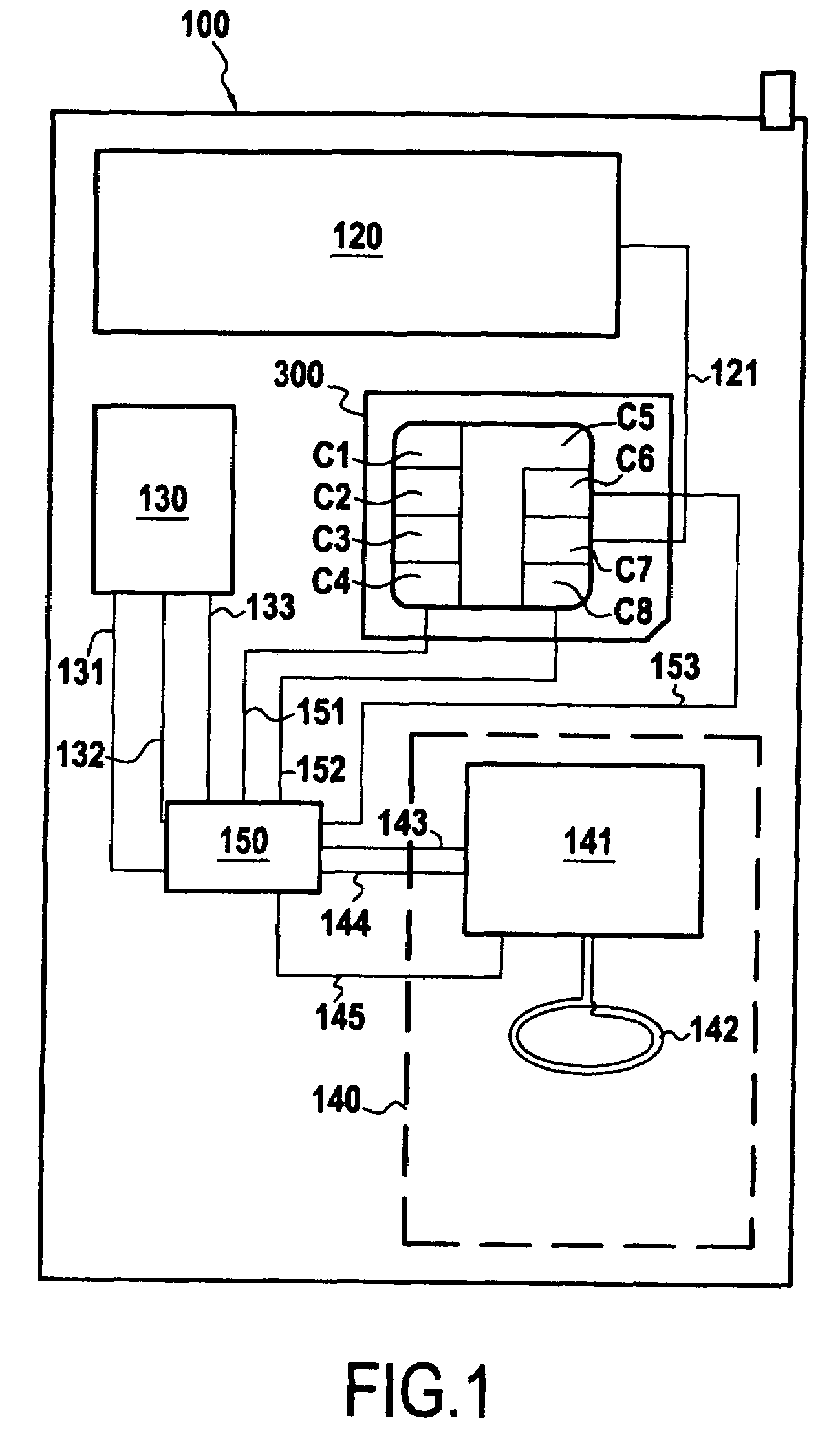
[0047]FIG. 2 shows a functional architecture of a mobile terminal 100 in which the invention can be implemented in accordance with one embodiment.

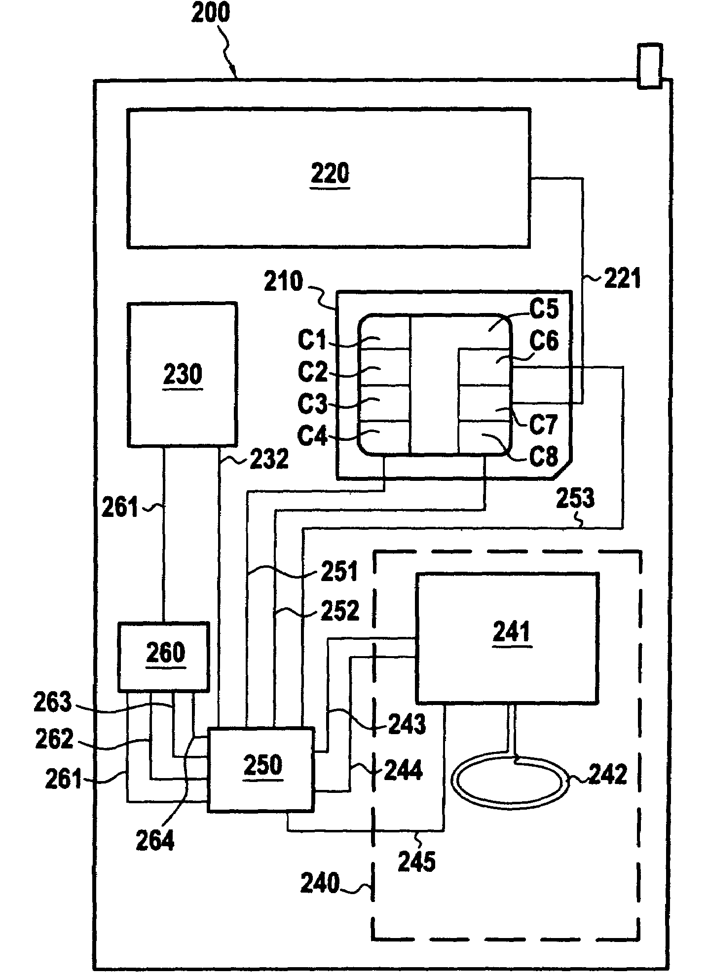
[0048]In FIG. 1, the mobile terminal, here a mobile telephone 100, includes a subscriber smart card 300, a digital baseband processor (DBB) 120 enabling data / voice to be sent / received over the mobile telephone network (GSM / GPRS), an application processor 130, a near-field communication (NFC) module 140, and a switching controller 150.

[0049]To keep the description simple, the other well-known software / hardware elements of a mobile telephone (user interface (keypad, screen, microphone, loudspeaker), operating system, etc.) are not shown in FIG. 1.

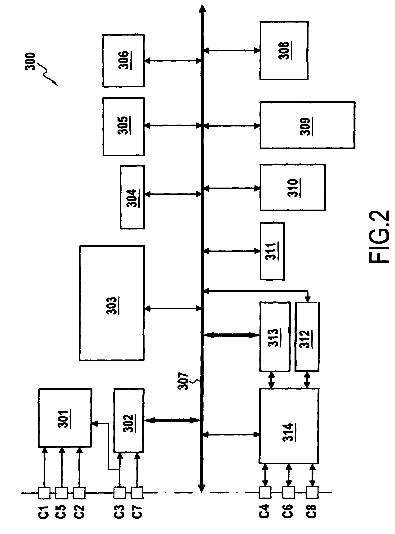
[0050]The subscriber smart card 300 (either a subscriber identity module (SIM) card, or a universal subscriber identity module (USIM) ...


PUM


Abstract

A contact allocation method for a subscriber smart card (300) in a mobile terminal (100) fitted with said card, the mobile terminal including at least first and second electronic modules (130, 140) suitable for communicating with the subscriber smart card (300) using respective first and second communications protocols. To enable the way in which the contacts of the subscriber smart card (300) are allocated to be managed dynamically, the card is connected to the first and to the second electronic modules (130, 140) in alternation by selectively connecting at least one contact (C4) of said card to the first or to the second electronic module (130, 140).

Description

RELATED APPLICATIONS[0001]This is a U.S. National Phase Application under 35 USC 371 of International Application PCT / IB2007 / 051052, filed on Mar. 26, 2007.[0002]This application claims the priority of French application no. 06 / 51206 filed on Apr. 5, 2006, and the content of which is hereby incorporated by reference.FIELD OF THE INVENTION[0003]The present invention relates to the field of mobile telephony, and more particularly it relates to the functional architecture of a mobile terminal and to managing the electrical contacts of the subscriber smart card present in the terminal.PRIOR ART[0004]A mobile telephone is made up of various elements (keypad / screen, microphone / loudspeaker, radiocommunication element (e.g. of the global system for mobiles (GSM) type), etc.) that are dedicated to the various functions made available to the user. Amongst these various elements there is a subscriber smart card known as a subscriber identity module (SIM) or as a universal subscriber identity m...

Claims


Application Information

Patent Timeline
Patent Type & Authority Patents(United States)
IPC IPC(8): H04B1/38H04M1/00H04M1/72409
CPCG06K7/10297G06K19/0723G06K19/07733
Inventor MOREL, OLIVIERKERDRAON, ALANBRIOT, OLIVIERMAUGARS, PHILIPPE
Owner ST ERICSSON SA
Learn More