
Downhole sanding analysis tool

a sanding analysis and tool technology, applied in the direction of material analysis using wave/particle radiation, instruments, and borehole/well accessories, etc., can solve the problems of sand and hydrocarbon fluids, pipe damage, and other related oil production or exploration equipment, filling the well and stopping production,

Inactive Publication Date: 2013-01-29
SCHLUMBERGER TECH CORP
View PDF38 Cites 8 Cited by
  • Summary
  • Abstract
  • Description
  • Claims
  • Application Information

AI Technical Summary

Benefits of technology

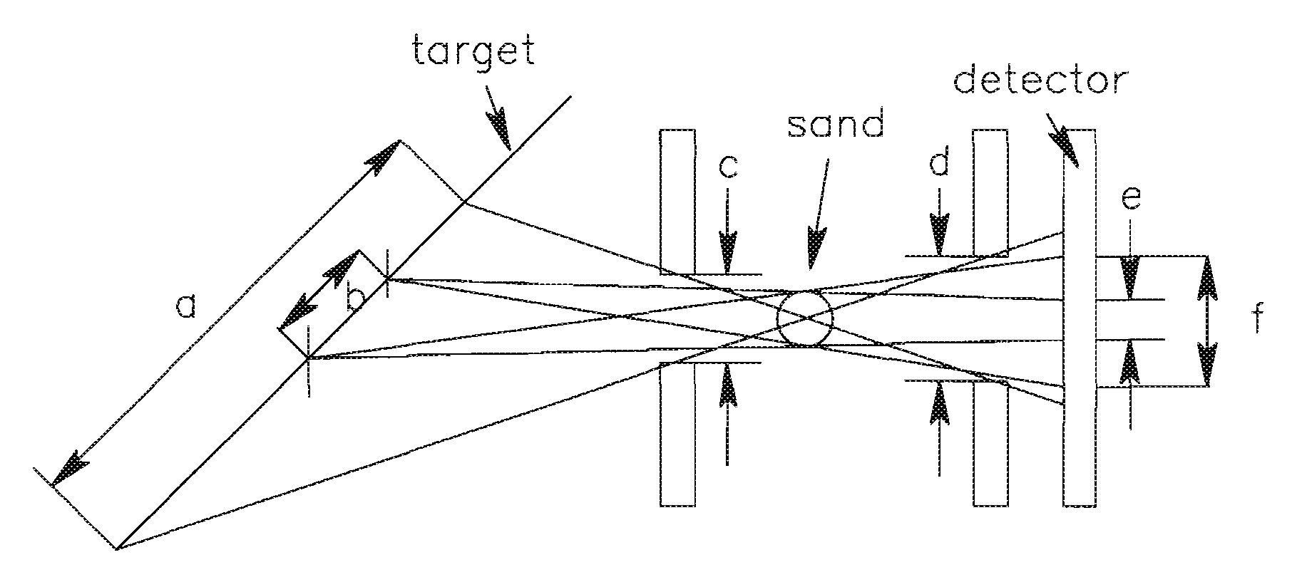
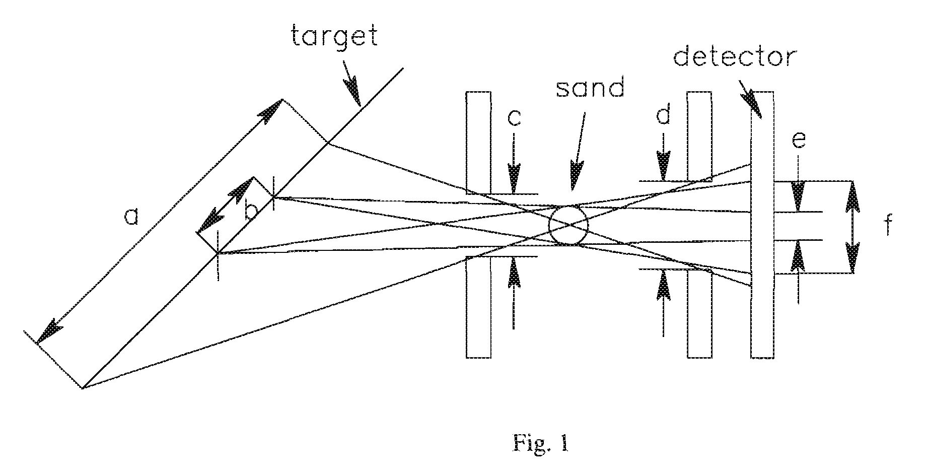
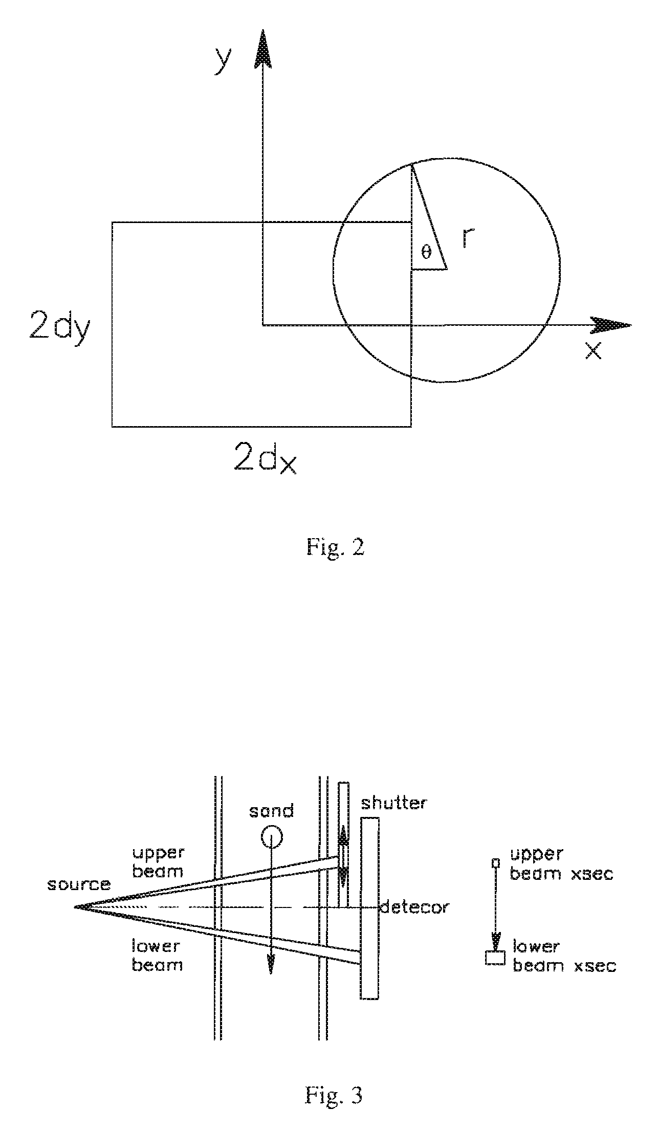
The patent describes an analyzing device for detecting particles in a fluid within a medium, such as sand or gas bubbles, and measuring their characteristics. The device uses sensing beams, such as x-rays or optical light beams, to detect the particles as they pass through the medium. The device can detect the size, velocity, and distribution of the particles, as well as the uniformity of their size and population. The device can also detect the gas bubbles in the fluid. The analyzing device can be used in various applications, such as in oil field applications or detecting sand grains in a sand production process.

Problems solved by technology

For example, sand can cause damage to pipes, pumps, valves, fluid treating installations on the surface, and other related oil production or exploration equipment.
Also the production of sand may result in clogged well lines that can result in filling in the well and stopping production.
Also, sand can also be present with hydrocarbon fluids when produced in gravel pack operations which are experiencing partial or complete failure.
However, one disadvantage of such an arrangement is that an accurate measure of particle size is not obtained, since the various impact signals are merely sorted into a number of ranges dictated by the threshold levels.
At least one disadvantage over the above-note prior art is that sonic techniques generally detect the presence of sand particles, but not other attributes, e.g., grain sizes, velocities, etc., all of which, among other things, are important to assess the potential erosion, for example to oil field applications such as pipes and / or equipment.
Further, sonic techniques are also not sensitive, if at all, when the sand population is low.

Method used


Image

  • Downhole sanding analysis tool
  • Downhole sanding analysis tool
  • Downhole sanding analysis tool

Examples


Embodiment Construction

[0057]The particulars shown herein are by way of example and for purposes of illustrative discussion of the embodiments of the present invention only and are presented in the cause of providing what is believed to be the most useful and readily understood description of the principles and conceptual aspects of the present invention. In this regard, no attempt is made to show structural details of the present invention in more detail than is necessary for the fundamental understanding of the present invention, the description taken with the drawings making apparent to those skilled in the art how the several forms of the present invention may be embodied in practice. Further, like reference numbers and designations in the various drawings indicated like elements.

[0058]The present invention is directed to an analyzing device for detecting particles in a fluid within a medium. The analyzing device includes: a source adapted to transmit signals into the medium; at least one detector ada...


PUM


Abstract

Methods and devices for detecting particles in a fluid within a medium, such the analyzing device includes: a source adapted to transmit signals into the medium; at least one detector adapted to detect signals transmitted from the source such that the at least one detector and the source are structured and arranged on opposite sides of the medium; at least one processing unit in communication with the at least one detector and adapted to produce a plurality of output signals representative of one of at least one particle characteristic or one or more particle property.

Description

BACKGROUND OF THE INVENTION[0001]1. Field of the Invention[0002]The invention generally relates to methods, systems and devices for detecting solid particles in a flowing fluid within a medium.[0003]2. Background of the Invention[0004]Methods and equipment for detecting solid particles in a flowing fluid is known already, where solid particles such as sand grains are often entrained in a flowing fluid that is recovered from an underground formation. For example, sand can cause damage to pipes, pumps, valves, fluid treating installations on the surface, and other related oil production or exploration equipment. Also the production of sand may result in clogged well lines that can result in filling in the well and stopping production. When this clogging occurs, the production of all oil wells feeding into the separator tanks must be stopped. Generally, the presence of sand can be dependent upon how an oil related fluid (such as gas and / or liquid hydrocarbons) was produced and the natu...

Claims


Application Information

Patent Timeline
Patent Type & Authority Patents(United States)
IPC IPC(8): G06F19/00
CPCG01N15/0205G01N21/85G01N21/94G01N23/12G01N2223/641G01N23/083
Inventor CHEN, FELIXCORRIS, GARY
Owner SCHLUMBERGER TECH CORP
Learn More