
Multi-purpose vacuum unit

a vacuum unit and multi-purpose technology, applied in the direction of cleaning equipment, tank vehicles, transportation items, etc., can solve the problems of added cost, added cost, and cost of building and operating, and achieve the effect of convenient operation

Inactive Publication Date: 2013-02-05
ECOTECH SERVICE
View PDF80 Cites 5 Cited by
  • Summary
  • Abstract
  • Description
  • Claims
  • Application Information

AI Technical Summary

Benefits of technology

The invention provides an apparatus for sucking fluid from a hard surface, such as a carwash or an airport tarmac. The apparatus includes a squeegee structure that moves across the surface and collects fluid, connected to a tank through vacuum inlets. The apparatus also has a fluid flow structure that connects to the tank, allowing for efficient operation on both shallow and deep liquid pools. Additionally, the invention provides an apparatus for vacuuming fluid from a hard surface that can be towed behind a vehicle, with the ability to adjust to different hitch heights. This feature provides versatility and flexibility for use in various environments, such as airports.

Problems solved by technology

Units which have been available prior to the present invention have required very powerful suction units, which are costly to build and to operate.
The special-purpose truck chassis, with its own power train, adds further cost.
Moreover, the fluids tend to accumulate on the pavement in uneven pools, with shallow and deep portions.
The suction cleaner may work well on deep liquid as, for example, a pool more than an inch deep, but work poorly on shallow liquid or vice-versa.

Method used


Image

  • Multi-purpose vacuum unit
  • Multi-purpose vacuum unit
  • Multi-purpose vacuum unit

Examples


Embodiment Construction

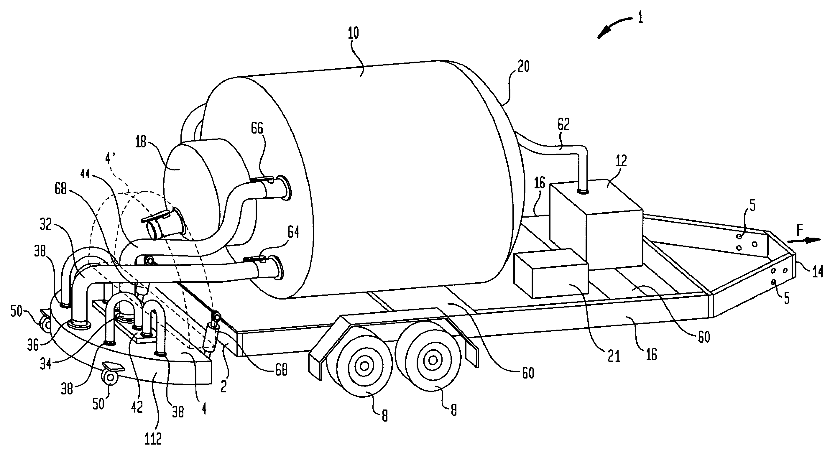
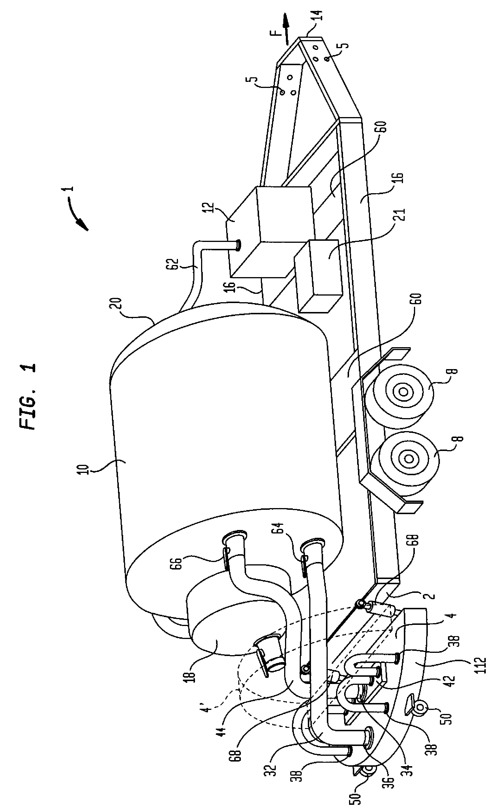
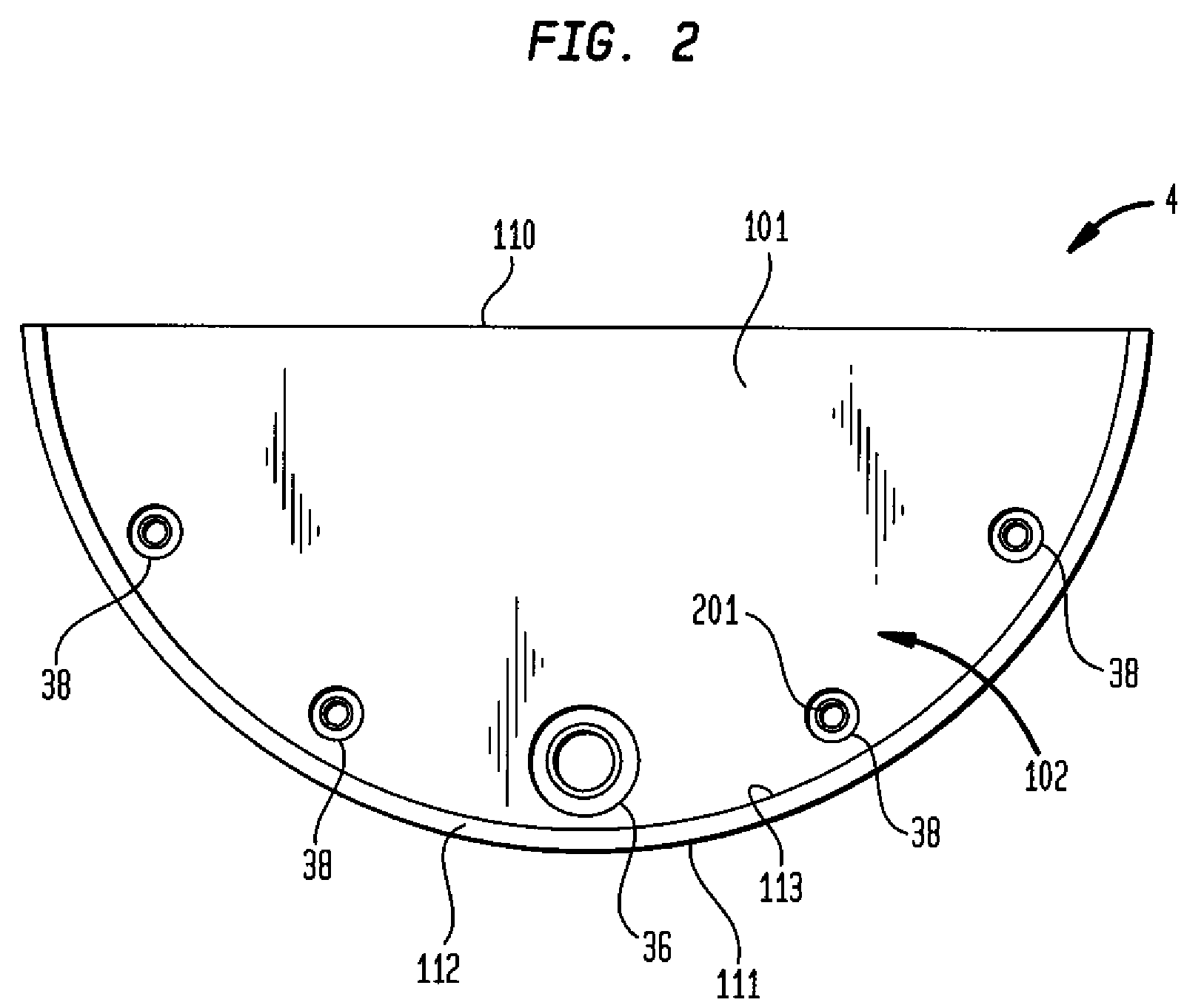
[0014]Apparatus according to one embodiment of the invention (FIG. 1) is intended for suctioning or vacuuming of fluid off of a hard surface. The apparatus can be used to vacuum fluid such as airplane de-icing fluid. The apparatus includes a trailer frame 1 constructed of steel. In this embodiment, the trailer is generally rectangular, but is not limited to this shape. The trailer frame has a front end 14, a rear end 2 and two side members 16 extending between the front and rear ends. Cross members 60 extend between the side members. The lengthwise dimension of the trailer is considerably greater than the height of the trailer frame. Wheels 8 are mounted to the trailer frame, and allow the trailer frame to be pulled over a surface in the forward direction. The side members 16 have attachment sites comprising two sets of holes 5 for the attachment of interchangeable trailer hitch assemblies. In the particular embodiment shown, each set of holes includes three holes.

[0015]The apparatu...


PUM


Abstract

A suction apparatus for retrieving liquids such as aircraft deicing fluid from a paved surface. The apparatus may have a squeegee structure with multiple inlets for fluid, and a fluid flow structure which can selectively connect only certain inlets to a suction tank. A large inlet can be used in deep fluids, whereas multiple smaller inlets can be used to retrieve a shallow layer of liquid. The inlets may be adjustable relative to the squeegee structure. The apparatus may be mounted on a trailer, and the trailer may be equipped with a hitch that can maintain the trailer in a predetermined level attitude regardless of the height of the hitch on the towing vehicle.

Description

BACKGROUND OF THE INVENTION[0001]It is often necessary to remove liquids from paved surfaces. In particular, it is presently the practice to de-ice aircraft by spraying the aircraft with deicing liquids such as glycols while the aircraft are parked on a paved surface such as a taxiway or ramp. The liquid which drains from the aircraft accumulates on the paved surface. This liquid must be collected so that it does not run into storm drains or off the pavement and into the ground water.[0002]It has been proposed heretofore to use a high-powered vacuum cleaner mounted on a special-purpose truck chassis with its own motive power to collect the liquid. Units which have been available prior to the present invention have required very powerful suction units, which are costly to build and to operate. The special-purpose truck chassis, with its own power train, adds further cost. Attempts have been made heretofore to use suction cleaning units mounted on trailers which can be pulled by an or...

Claims


Application Information

Patent Timeline
Patent Type & Authority Patents(United States)
IPC IPC(8): A47L7/00
CPCE01H1/108
Inventor COPPOLA, JOHN R.COPPOLA, FRANK G.
Owner ECOTECH SERVICE
Learn More