
Method and apparatus for probing a computer bus

a computer bus and probe technology, applied in the field of probes, can solve the problems of affecting the efficiency of the disassembly of the microprocessor bus. achieve the effect of facilitating the efficient operation of the disassembly of the microprocessor bus

Inactive Publication Date: 2008-03-04
TEKTRONIX INC
View PDF6 Cites 0 Cited by
  • Summary
  • Abstract
  • Description
  • Claims
  • Application Information

AI Technical Summary

Benefits of technology

The invention provides a way to detect and fix a problem in a computer chip called a strobe phase inversion. This can happen when data is transferred between two parts of the chip. The invention can detect the problem and fix it by changing the order of the data and removing extra samples. This means that the chip can work more efficiently and with less errors.

Problems solved by technology

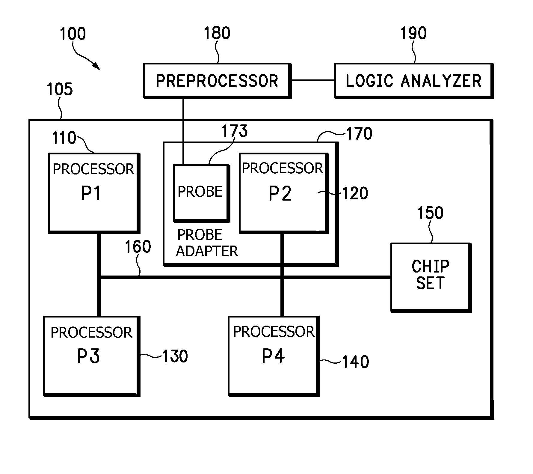
However, these timing relationships may be violated when the processor in the probe adapter drives the bus.
A logic analyzer monitoring bus traffic faces yet another signal timing problem.
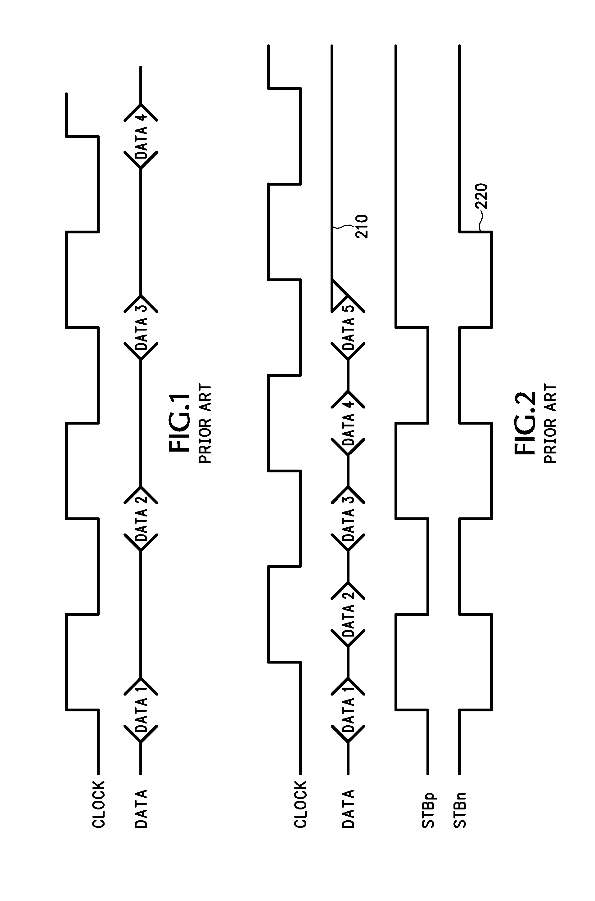
While this transfer method has been widely used, it tends to be too slow for today's high-speed applications.
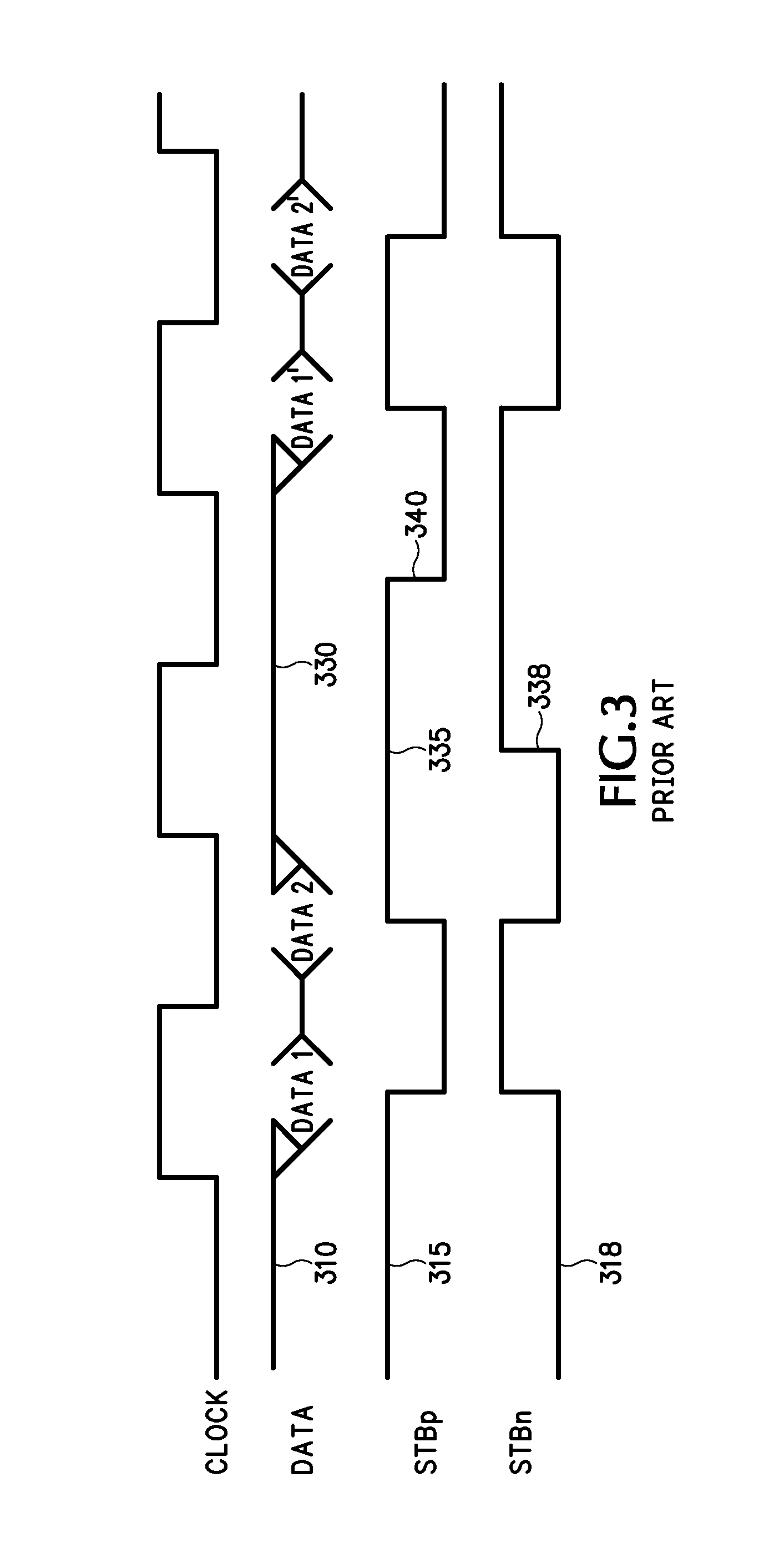
It is important to note that since data capture is controlled by negative-going edges of the strobes, the predrive transition causes an erroneous acquisition of invalid data.
If a microprocessor probe is latching this data into memory devices such as flip-flops, a strobe phase reversal will cause the data to be presented to the Logic Analyzer in a swapped order and may also result in an extra data sample.
However, this solution is undesirable for at least three distinct reasons.
First, this solution puts an extra burden on the disassembly software in the Logic Analyzer to reorder the data whenever a strobe phase inversion takes place.
This extra burden causes a significant increase in the time it takes the microprocessor disassembly software to present to the user the transactions that are occurring on the data bus.
Second, this solution doesn't store the data as it was transferred across the bus.
Third, this solution operates in a post-processing mode; it does not operate in real time.
Since triggering must occur in real time, using this scheme would make it difficult, if not impossible, to trigger on data affected by such a strobe phase reversal.

Method used


Image

  • Method and apparatus for probing a computer bus
  • Method and apparatus for probing a computer bus
  • Method and apparatus for probing a computer bus

Examples


Embodiment Construction

[0029]In order to detect that a strobe phase inversion has taken place, it is necessary to monitor specific control signals on the data bus that identify when the inversion will occur. These control signals, based on a certain sequential pattern, will identify when the data strobes will change phase. FIGS. 4, 5, and 6 show, in block diagram form, circuitry that is capable of detecting when a strobe phase inversion takes place, and tracks predrive condition for the next data transfer. The terms “strobe phase reversal”, “strobe phase shift” and “strobe phase inversion”, as used herein, have the same meaning, and are used interchangeably.

[0030]Referring to FIG. 4, control signals are montored by Digital Circuit 1, sequentially clocked by the main bus clock. When a certain sequence of events occurs on the control signals, the digital circuit will assert either the Strobe Invert signal or the Phase Reset signal. The sequence of events to determine whether to assert the Strobe Invert or t...


PUM


Abstract

The subject invention facilitates the efficient operation of the disassembly of the microprocessor bus by providing an apparatus and method for detecting and correcting a strobe phase inversion and predrive filtering in a 2× source synchronous data transfer bus. Apparatus according to the subject invention detects a data strobe inversion in a source synchronous 2× data bus and corrects for this inversion by reordering the received data as well as filtering predrive effects in real time. Specifically, this apparatus according to the subject invention monitors bus traffic in a multiprocessor environment and correctly captures all double data rate exchanges regardless of the source IC or destination IC in the system.

Description

CLAIM OF PRIORITY[0001]The subject application claims priority from U.S. Provisional Patent Application Ser. No. 60 / 485,930, attorney docket number 7719-US0 METHOD AND APPARATUS FOR STROBE PHASE INVERSION DETECTION AND CORRECTION (Fenton, et al.), filed 8 Jul. 2003.FIELD OF THE INVENTION[0002]The subject application generally concerns the field of probing a computer bus with a logic analyzer probe, and specifically concerns an apparatus and method for more accurately acquiring data from a high-speed computer bus.BACKGROUND OF THE INVENTION[0003]When investigating the operation of a computer architecture (i.e., troubleshooting or debugging the system hardware or software), it is commonplace for an engineer to employ a logic analyzer to capture data traffic on the system bus. This may be done by unplugging an IC processor from its socket, plugging in a probe adapter, and reinstalling the processor in a socket of the probe adapter. In this way, the logic analyzer gets access to the sys...

Claims


Application Information

Patent Timeline
Patent Type & Authority Patents(United States)
IPC IPC(8): G01R31/28G01R31/02G06F11/00G11C5/00
CPCG06F11/0745G06F11/0751
Inventor FENTON, JAMES M.TAYLOR, KEVINMARKOZEN, GENE L.
Owner TEKTRONIX INC
Learn More