
System and method for improving the wear life of a brake shoe in the counterbalance system of a tilt-in window

Active Publication Date: 2013-02-12
LESJOFORS US INC
View PDF29 Cites 13 Cited by
  • Summary
  • Abstract
  • Description
  • Claims
  • Application Information

AI Technical Summary

Benefits of technology

This patent describes brake shoe assemblies that are designed to attach to a coil spring and are positioned within curved edges of a brake guide track. The brake shoe's housing has two curved side edges that make contact with the guide track at a tangent when the brake is cocked. This design prevents the brake shoe from becoming worn out or becoming stuck in the guide track. In summary, this patent describes how to create brakes that offer better performance and durability.

Problems solved by technology

The weights counterbalanced the weight of the window sashes.
The use of weight wells, however, prevents insulation from being packed tightly around a window frame.
Furthermore, the use of counterbalance weights on chains or strings cannot be adapted well to tilt-in double-hung windows.
Second, the shoes engage curl springs.
Prior art shoes for curl spring counterbalance systems are typically complex assemblies.
The shoe binds in the guide track and the window becomes so difficult to open and close that it cannot be considered functional.
This cocked orientation also causes the brake shoe to wear against the window track in an uneven manner.
Over time, it often becomes more difficult for the oddly worn shoes to move up and down.

Method used


Image

  • System and method for improving the wear life of a brake shoe in the counterbalance system of a tilt-in window
  • System and method for improving the wear life of a brake shoe in the counterbalance system of a tilt-in window
  • System and method for improving the wear life of a brake shoe in the counterbalance system of a tilt-in window

Examples


Embodiment Construction

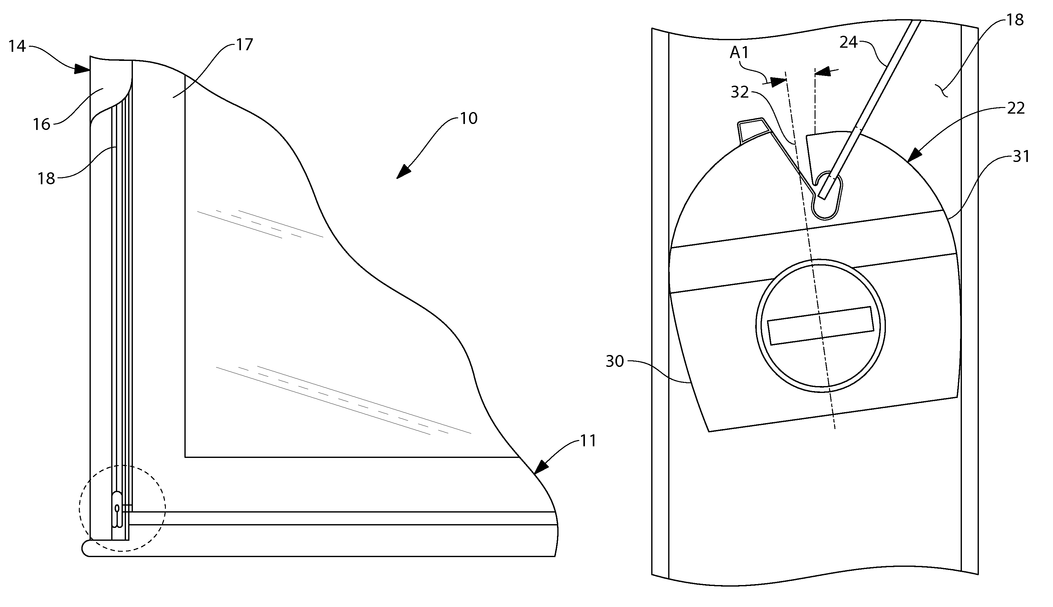
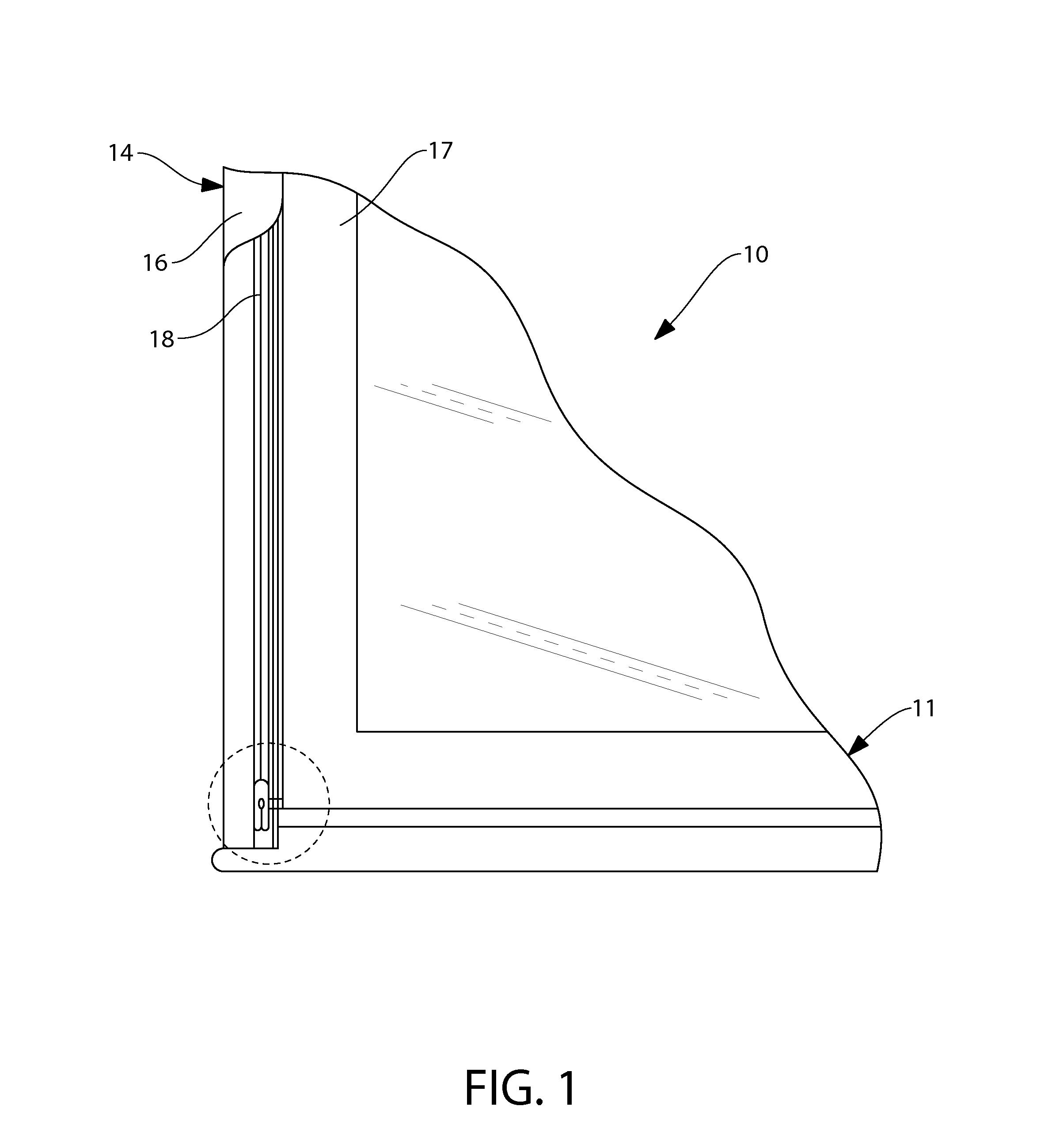
[0028]Referring to FIG. 1, there is shown an exemplary embodiment of a vinyl, tilt-in, double-hung window assembly 10. The window assembly 10 has two sashes 11, which include an upper sash and a lower sash. Each of the sashes 11 has two side elements 17. The sashes 11 are contained within a window frame 14. The window frame 14 has two vertical sides 16 that extend along the side elements 17 of both sashes 11. Within each of the vertical sides 16 of the window frame 14 is formed a guide track 18.

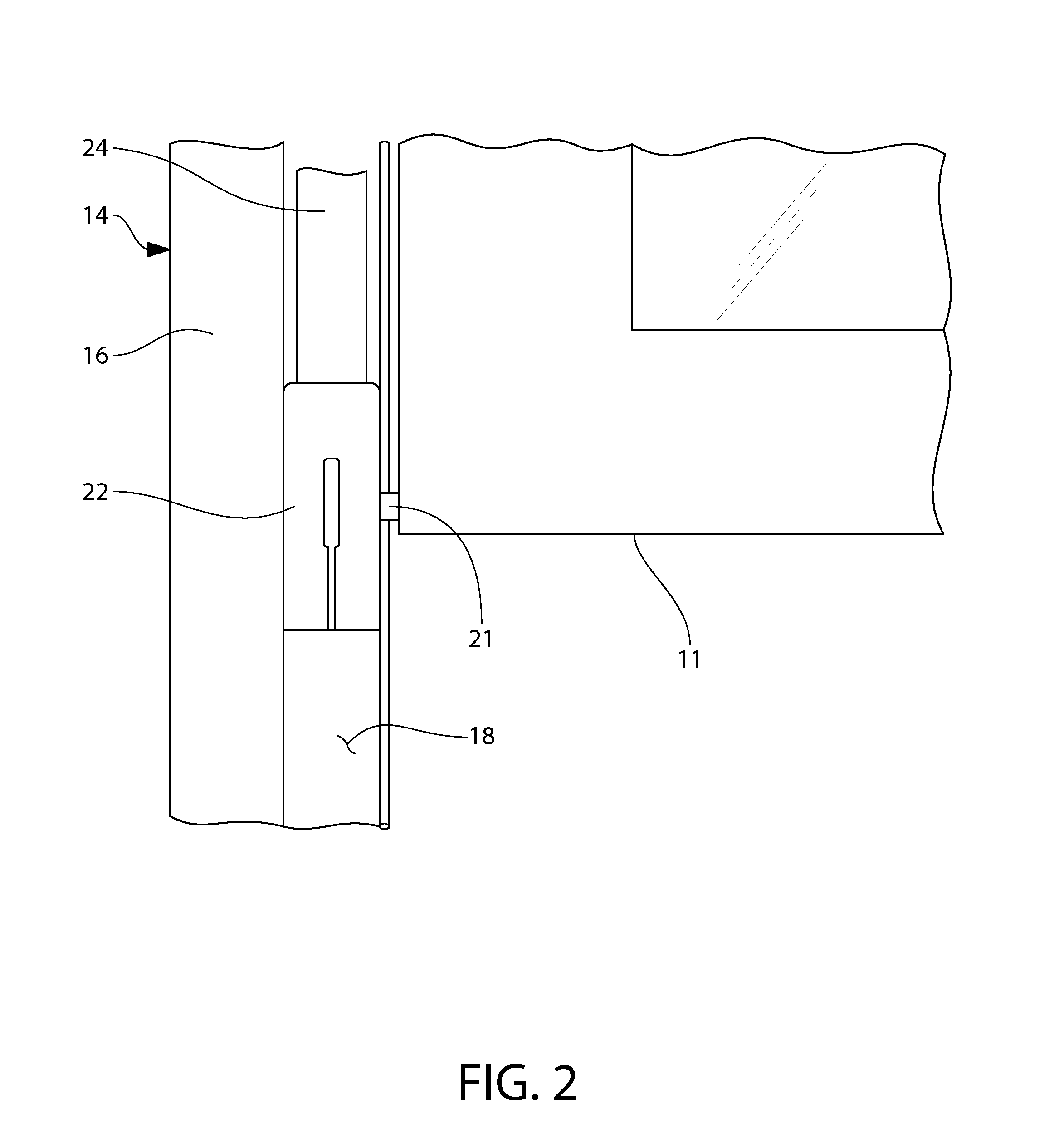
[0029]Referring to FIG. 2, it can be seen that the sash 11 has a tilt post 21 that extends out away from the side of the sash 11 and into the guide tracks 18 in the vertical sides 16 of the window frame 14. As is later explained in greater detail, a brake shoe assembly 22 is provided that attaches to the tilt post 21. The brake shoe assembly 22 serves two purposes. First, the brake shoe assembly 22 serves as a brake mechanism that locks the bottom of a sash 11 in place within the guide track ...


PUM


Abstract

A counterbalance system for a tilt-in window and its method of operation. Posts are provided on the sides of a tilt-in window sash that rotate when the sash is tilted. A brake structure is attached to each post. Each brake structure has a first contoured surface that rotates with the post when said sash is tilted. A second contoured surface is provided within the window track. The second contoured surface moves up and down in the track with the post but does not rotate with the post when the sash is tilted. When the window sash is tilted for cleaning, the first contoured surface moves against the second contoured surface within the window track. A cam action occurs that moves the first contoured surface away from the second contoured surface. This causes the brake structure to be biased against the track and lock in a fixed position within the track.

Description

RELATED APPLICATIONS[0001]This application is a continuation-in-part of U.S. patent application Ser. No. 11 / 072,122, entitled ROUNDED SHOE AND POSITION BRAKE ASSEMBLY FOR THE COUNTERBALANCE SYSTEM OF A TILT-IN WINDOW, filed Mar. 7, 2005 now U.S. Pat. No. 7,966,770.BACKGROUND OF THE INVENTION[0002]1. Field of the Invention[0003]In general, the present invention relates to counterbalance systems for windows that prevent open window sashes from moving under the force of their own weight. More particularly, the present invention system relates to the brake shoe component of the counterbalance systems for tilt-in windows.[0004]2. Description of the Prior Art[0005]There are many types and styles of windows. One of the most common types of window is the double-hung window. Double-hung windows are the window of choice for most home construction. A double-hung window consists of an upper window sash and a lower window sash. Either the upper window sash or the lower window sash can be selecti...

Claims


Application Information

Patent Timeline
IPC IPC(8): E05D15/22E05D15/24
CPCE05D13/08E05Y2900/148Y10T16/643Y10T16/6298Y10T16/642
Inventor KUNZ, JOHN R.
Owner LESJOFORS US INC
Learn More