
Yarn conveying system for circular knitting machines

a conveying system and yarn technology, applied in knitting, weft knitting, textiles and papermaking, etc., can solve the problems of slow weaving speed of the shuttle loom, broken yarns caused by the tension of the warp yarns drawing the yarn beam, and heavy yarn beam, etc., to achieve a low production of fabri

Inactive Publication Date: 2013-02-12
PAI LUNG MACHINERY MILL CO LTD
View PDF22 Cites 5 Cited by
  • Summary
  • Abstract
  • Description
  • Claims
  • Application Information

AI Technical Summary

Benefits of technology

The present invention relates to a system for weaving warp yarns in a shuttle loom to produce fabric. The technical effects of this invention are to improve fabric production efficiency and to regulate the tension of yarns during knitting operation. The invention includes a movement detection device with multiple sensors to detect the positions of different moving elements and to regulate the speed of the yarn conveying tray. Additionally, a yarn buffer device is provided to detect and regulate the tension of the yarns, ensuring high quality fabric production without being affected by too much or too little tension.

Problems solved by technology

Although the yarn beam is quite heavy, the weaving speed of the shuttle loom slows down and a great number of the warp yarns are drawn at the same time, broken yarns caused by the tension of the warp yarns drawing the yarn beam are seldom.
However, as the shuttle loom has a relatively slow weaving speed, production of denim is limited.

Method used


Image

  • Yarn conveying system for circular knitting machines
  • Yarn conveying system for circular knitting machines
  • Yarn conveying system for circular knitting machines

Examples


Embodiment Construction

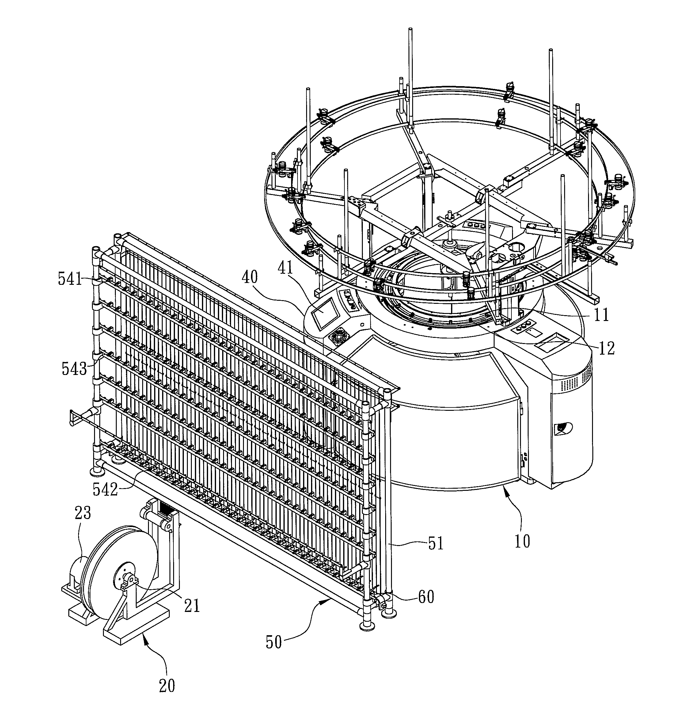
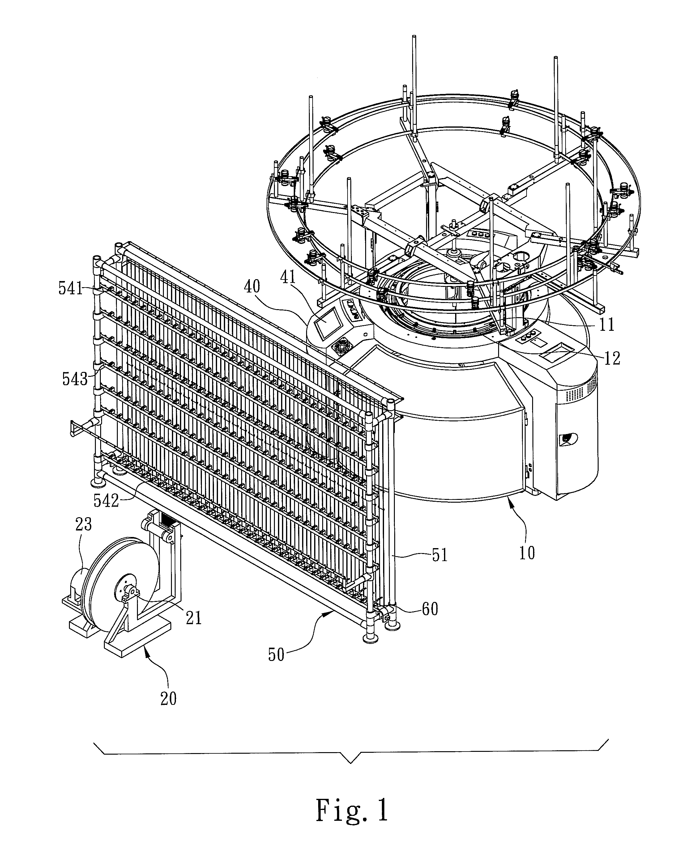
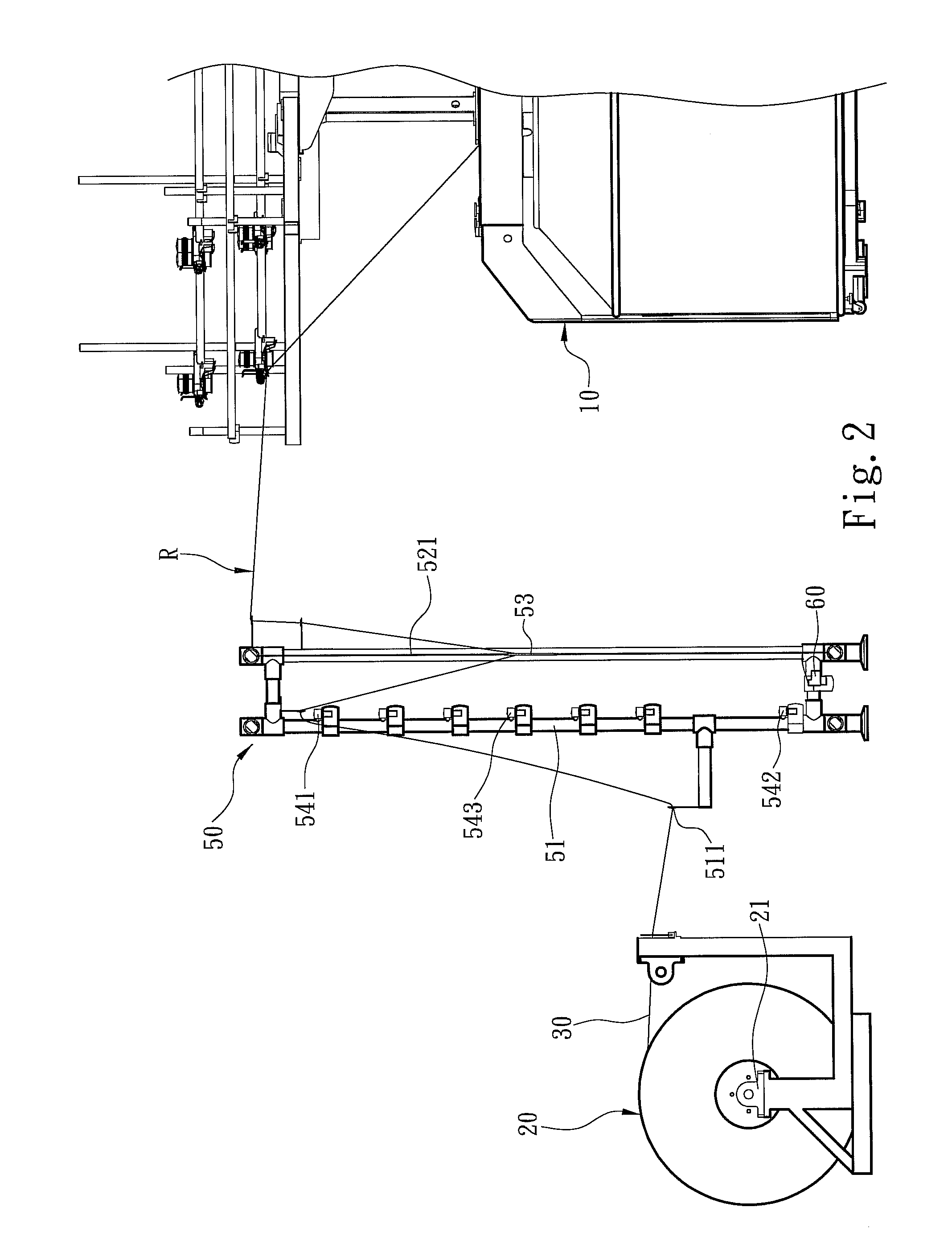
[0021]Please refer to FIGS. 1, 2 and 3 for an embodiment of the yarn conveying system of the invention. It is used on a circular knitting machine 10 which includes a needle cylinder 11 and at least one yarn feeder 12 arranged annularly on the needle cylinder 11. The circular knitting machine 10 further has a first power converter 13 and a main driving motor 14 receiving power output from the first power converter 13 to drive the yarn feeder 12 to perform yarn knitting. The first power converter 13 may be a DC to AC transformer.

[0022]In this embodiment, the circular knitting machine 10 also has a control unit 40 electrically connected to the first power converter 13 to output a yarn feeding signal S1 according to setting to the first power converter 13 to control the yarn feeding speed of the yarn feeder 12 driven by the main driving motor 14. The control unit 40 includes an operation interface 41 to receive user's input commands. The operation interface 41 can be a keyboard or a tou...


PUM


Abstract

A yarn conveying system includes a circular knitting machine, at least one yarn conveying tray and a control unit electrically connected to the circular knitting machine and yarn conveying tray. The circular knitting machine has a needle cylinder and at least one yarn feeder arranged annularly on the needle cylinder. The yarn conveying tray is wound by at least two separate yarns and includes a driving device to drive the yarn conveying tray rotating so that the yarns are supplied via a yarn conveying path to the yarn feeder. The control unit generates a yarn feeding signal to the circular knitting machine to control yarn feeding speed and a driving signal to the driving device to control rotational speed of the yarn conveying tray. Thus users can operate the control unit to control speed of the yarns supplied from the yarn conveying tray to the yarn feeder.

Description

FIELD OF THE INVENTION[0001]The present invention relates to a yarn conveying system for circular knitting machines and particularly to an active yarn conveying system for circular knitting machines.BACKGROUND OF THE INVENTION[0002]Denim is a coarse weave cotton cloth widely used on wear-resistant fabric for working and fashion clothes. The conventional technique of producing denim is winding a great number of warp yarns (such as 6000 pieces) on a single yarn beam and dyeing the yarns with Indigo, and coloring via a reducing agent to form an indigo color on the warp yarns.[0003]In general, the dyed indigo warp yarns wound on the yarn beam are woven via a shuttle loom. As the shuttle loom weaves the yarns, the yarn beam is drawn by the yarns to passively supply the warp yarns. Namely, the yarn beam is driven to rotate by the drawing force of the yarns woven on the shuttle loom. Although the yarn beam is quite heavy, the weaving speed of the shuttle loom slows down and a great number ...

Claims


Application Information

Patent Timeline
IPC IPC(8): D04B15/40
CPCD04B15/40
Inventor CHEN, SHIH-CHISHYU, JENQ-HUEYFU, HSUEH-CHEN
Owner PAI LUNG MACHINERY MILL CO LTD
Learn More