
Endoscope system, processor device, operation method, and distance measurement device

Active Publication Date: 2016-06-30
FUJIFILM CORP
View PDF4 Cites 15 Cited by
  • Summary
  • Abstract
  • Description
  • Claims
  • Application Information

AI Technical Summary

Benefits of technology

The invention provides an endoscope system, processor device, operation method and distance measurement device that can measure the distance without adding an interferometer. This means that the device is more cost-effective and flexible in design.

Problems solved by technology

In a case in which the interferometer for measuring the observation distance is provided as disclosed in JP1997-294708A (JP-H09-294708A), there is a problem that the cost is increased.
In addition, in the endoscope system disclosed in JP1997-294708A (JP-H09-294708A), space for placing a member that forms the interferometer is required even though it is difficult for the insertion unit of the endoscope to have a large diameter.
For example, in the case of providing the interferometer for measuring the observation distance, size reduction and space saving are difficult compared with a case in which the interferometer is not present.

Method used


Image

  • Endoscope system, processor device, operation method, and distance measurement device
  • Endoscope system, processor device, operation method, and distance measurement device
  • Endoscope system, processor device, operation method, and distance measurement device

Examples


first embodiment

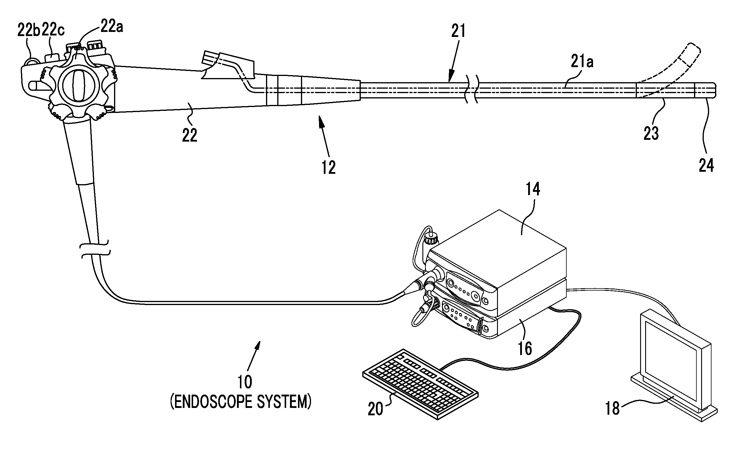
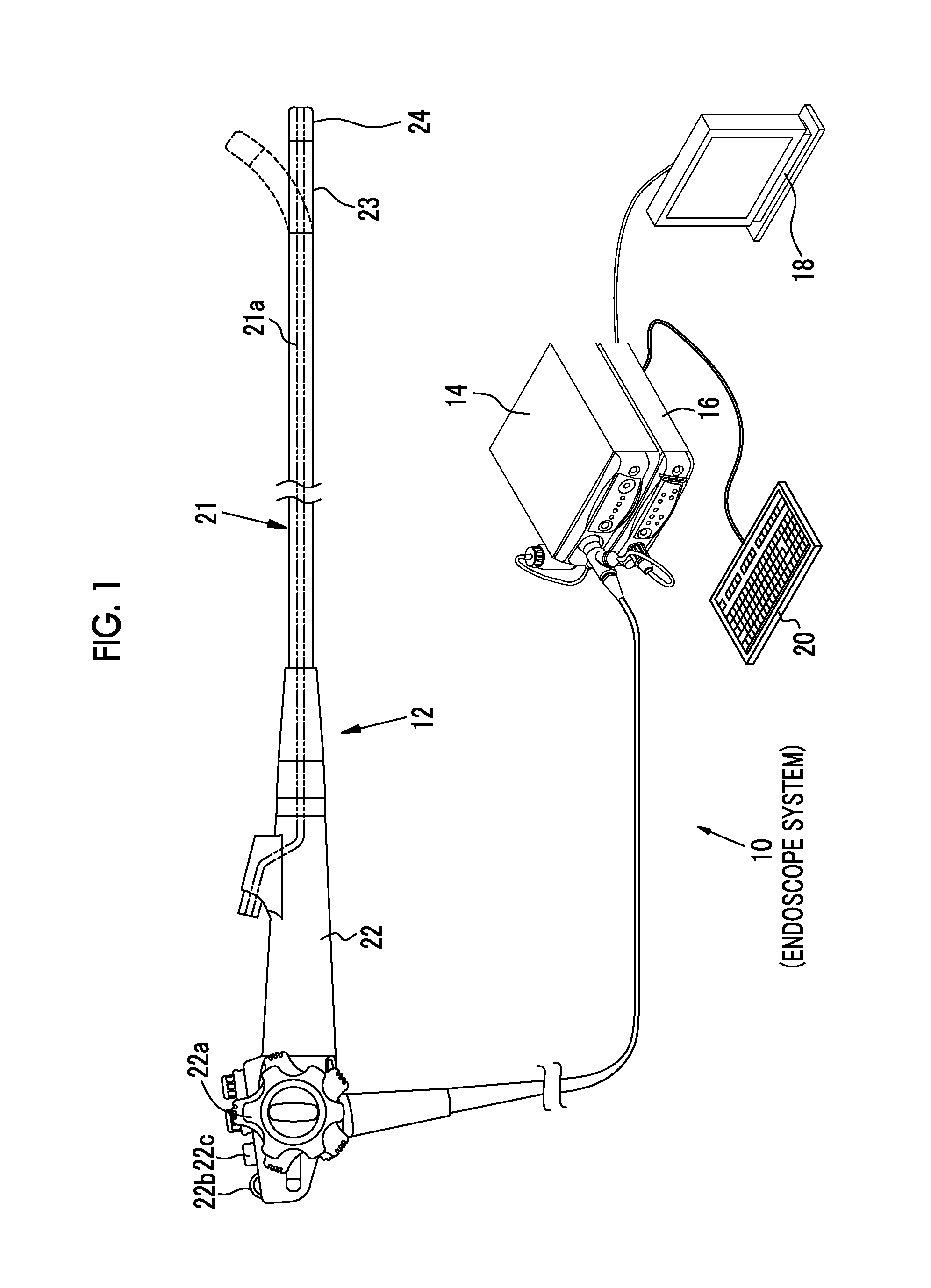
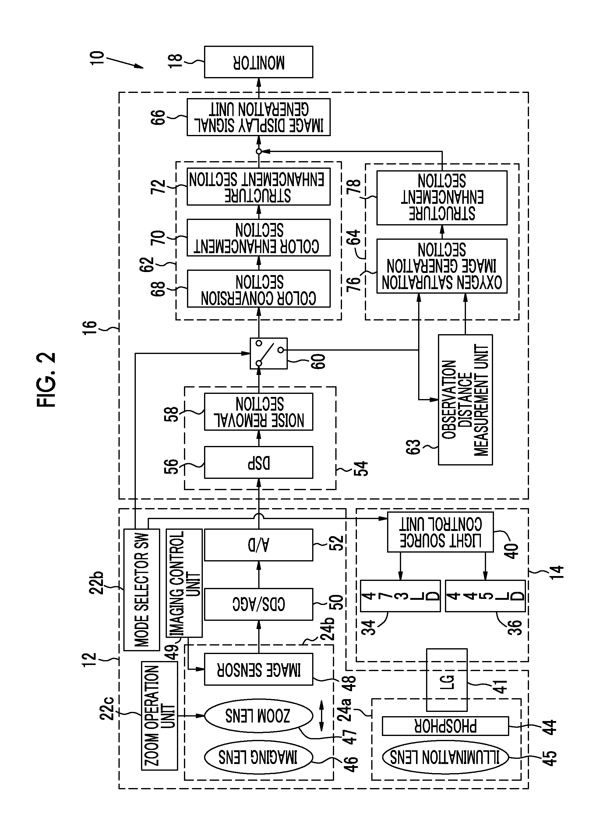
[0057]As shown in FIG. 1, an endoscope system 10 of a first embodiment includes an endoscope 12, a light source device 14, a processor device 16, a monitor 18, and a console 20. The endoscope 12 is optically connected to the light source device 14, and is electrically connected to the processor device 16. The endoscope 12 includes an insertion unit 21 that is inserted into a subject, an operation unit 22 provided at the proximal end of the insertion unit 21, and a bending portion 23 and a distal portion 24 that are provided at the distal side of the insertion unit 21. By operating an angle knob 22a of the operation unit 22, the bending portion 23 is bent. Through the bending operation, the distal portion 24 is directed toward a desired direction.

[0058]A forceps channel 21a for inserting a treatment instrument, such as forceps, is provided in the insertion unit 21. An inlet of the forceps channel 21a is provided in the operation unit 22, and an outlet is provided in the distal portio...

second embodiment

[0150]As shown in FIG. 25, in a light source device 14 of an endoscope system 300, a light emitting diode (LED) light source unit 301 and an LED light source control unit 304 are provided instead of the first and second blue laser light sources 34 and 36 and the light source control unit 40. In addition, the phosphor 44 is not provided in an illumination optical system 24a of the endoscope system 300. Other than these, the endoscope system 300 is the same as the endoscope system 10 of the first embodiment.

[0151]The LED light source unit 301 includes an R-LED 301a, a G-LED 301b, and a B-LED 301c as light sources for emitting light limited to a specific wavelength band. As shown in FIG. 26, the R-LED 301a emits red band light (hereinafter, simply referred to as red light) in a red region of 600 nm to 720 nm, and the G-LED 301b emits green band light (hereinafter, simply referred to as green light) in a green region of 480 nm to 620 nm. The B-LED 301c emits blue band light (hereinafter...

third embodiment

[0158]As shown in FIG. 29, in a light source device 14 of an endoscope system 400, a broadband light source 401, a rotary filter 402, and a rotary filter control unit 403 are provided instead of the first and second blue laser light source 34 and 36 and the light source control unit 40. An image sensor 405 of the endoscope system 400 is a monochrome imaging device in which no color filter is provided. Other than these, the endoscope system 400 is the same as the endoscope systems of the first to third embodiments.

[0159]The broadband light source 401 is, for example, a xenon lamp or a white LED, and emits white light having a wavelength in a wavelength band ranging from blue to red. The rotary filter 402 includes a normal observation mode filter 410 and a special observation mode filter 411 (refer to FIG. 30), and can move in a radial direction between a first position for normal observation mode to place the normal observation mode filter 410 on the optical path, in which the white ...


PUM


Abstract

There are provided an endoscope system, a processor device, an operation method, and a distance measurement device for accurately measuring the observation distance even if a colorant or residues are present in a subject. An endoscope system 10 includes a light source device 14, an endoscope 12, and an observation distance measurement unit 63. The light source device 14 emits signal light, which has a wavelength band absorbed by hemoglobin contained in the subject, to the subject. The endoscope 12 has an image sensor 48 that images the subject with reflected light of the signal light and outputs an image signal. The observation distance measurement unit 63 measures the observation distance based on the image signal.

Description

CROSS-REFERENCE TO RELATED APPLICATIONS[0001]This application is a Continuation of PCT International Application No. PCT / JP2014 / 072186 filed on Aug. 25, 2014, which claims priority under 35 U.S.C §119(a) to Japanese Patent Application No. 2013-202544 filed on Sep. 27, 2013. Each of the above application(s) is hereby expressly incorporated by reference, in its entirety, into the present application.BACKGROUND OF THE INVENTION[0002]1. Field of the Invention[0003]The present invention relates to an endoscope system, a processor device, an operation method, and a distance measurement device for observing the inside of a subject.[0004]2. Description of the Related Art[0005]In the medical field, it is common to perform diagnosis using an endoscope system. The endoscope system includes a light source device that generates light for irradiating a subject, an endoscope that images the subject, and a processor device that performs processing on an image signal obtained by imaging the subject,...

Claims


Application Information

Patent Timeline
IPC IPC(8): A61B1/04A61B1/00A61B5/145A61B1/06A61B5/1459A61B5/1455
CPCA61B1/043A61B5/1459A61B5/14556A61B1/00009A61B1/0661A61B1/0653A61B5/14546A61B1/0638A61B1/0684A61B1/3137A61B1/000094
Inventor SHIRAISHI, YASUSHI
Owner FUJIFILM CORP
Learn More