Resistor shield to minimize crosstalk and power supply interference

a resistance shield and power supply technology, applied in the manufacture of final products, electrical apparatus construction details, instruments, etc., can solve the problems of further unwanted effects on the input signals being measured by the power meter, measurement variability, etc., and achieve the effect of reducing the effects of external influences and high accuracy of the power meter

Active Publication Date: 2013-02-12
SCHNEIDER ELECTRIC USA INC
View PDF8 Cites 12 Cited by
  • Summary
  • Abstract
  • Description
  • Claims
  • Application Information

AI Technical Summary

Benefits of technology

[0003]A highly accurate power meter is achieved by reducing the effects of external influences such as EMI due to high-power components in the meter's power supply and the effects of crosstalk from adjacent phase inputs to the power meter. To do so, aspects of the present disclosure propose to insert a shield composed of one or more shielded printed circuit boards (PCBs) having a conductive material inside the rigid or flexible printed circuit boards such that the shield exists in a path of the electromagnetic energy produced by the power supply and energy from crosstalk signals in adjacent phases. In an exemplary configuration, four resistors are disposed on a main printed circuit board inside a housing of the power meter. A PCB shield is placed between each of the four resistors and one PCB shield is placed on either side of the outermost resistors. The power supply is disposed on a circuit board that is placed near (such as above) the main PCB, such that electromagnetic energy produced by high-power components of the power supply will create field lines, the strongest of which will tend to run generally across the surface of the main PCB and couple with the exposed voltage input resistors. Without a PCB shield, these fields would couple directly with the voltage signals passing through the input resistors, interfering with these signals and causing variability in the measurements. By inserting a PCB shield between each resistor and opposite the outermost resistors, a barrier is created to the electromagnetic fields produced by the power supply or other nearby electronic components, shielding the resistors from their effects. Though some fields may couple over the tops of the resistors, these fields are much weaker and can be ignored. However, an optional cover can be placed over the PCB shields and corresponding resistors to protect the resistors. The cover can also include a conductive material to provide further shielding over the tops of the resistors.
[0004]A resistor sandwiched between two grounded PCB shields can look and behave like a capacitor, creating further unwanted effects on the input signals being measured by the power meter. Aspects of the present disclosure propose to angle the resistors so that they are diagonally spaced between adjacent pairs of PCB shields, forming a N-shape via each resistor and pair of PCB shields. This locks the resistor in place, which serves two purposes: First, it prevents the resistor pins from being flexed and avoids weakening of the resistor pins. Secondly, it fixes the distance between the PCB shield and the resistor, so that any parasitic capacitance created between the resistor and PCB shields will be of a fixed value, which can then be compensated for. Alternately, the resistors can be oriented so that they are parallel with adjacent sides of the PCB shields providing the components are fixed and supported to maintain consistent spacing.
[0005]In another configuration, the PCB shield is composed of flexible materials, sometimes called a flex-PCB, with a flexible conductive material inside the dielectric material of the flex-PCB. In this configuration, the PCB shield is snaked over and between each resistor in a serpentine fashion to provide a shield both over and surrounding both sides of each resistor. This configuration protects each resistor from electromagnetic energy and energy due to crosstalk from both sides and from the tops of each resistor. The main PCB itself forms a barrier to any unwanted energy (e.g., EMI or crosstalk) passing through the main PCB, so it is not necessary to shield the bottoms of each resistor, as they should be generally well-shielded against this unwanted energy. No cover is proposed in this configuration, though one is not precluded either.
[0006]The present disclosure without any further modifications to an existing power meter reduces the variability in the voltage input measurements from within 0.05% to less than 0.005%. Power meters using the aspects of the present disclosure will be poised to not merely satisfy but far exceed any applicable regulations, codes, or standards.

Problems solved by technology

Without a PCB shield, these fields would couple directly with the voltage signals passing through the input resistors, interfering with these signals and causing variability in the measurements.
A resistor sandwiched between two grounded PCB shields can look and behave like a capacitor, creating further unwanted effects on the input signals being measured by the power meter.

Method used


Image

  • Resistor shield to minimize crosstalk and power supply interference
  • Resistor shield to minimize crosstalk and power supply interference
  • Resistor shield to minimize crosstalk and power supply interference

Examples


Embodiment Construction

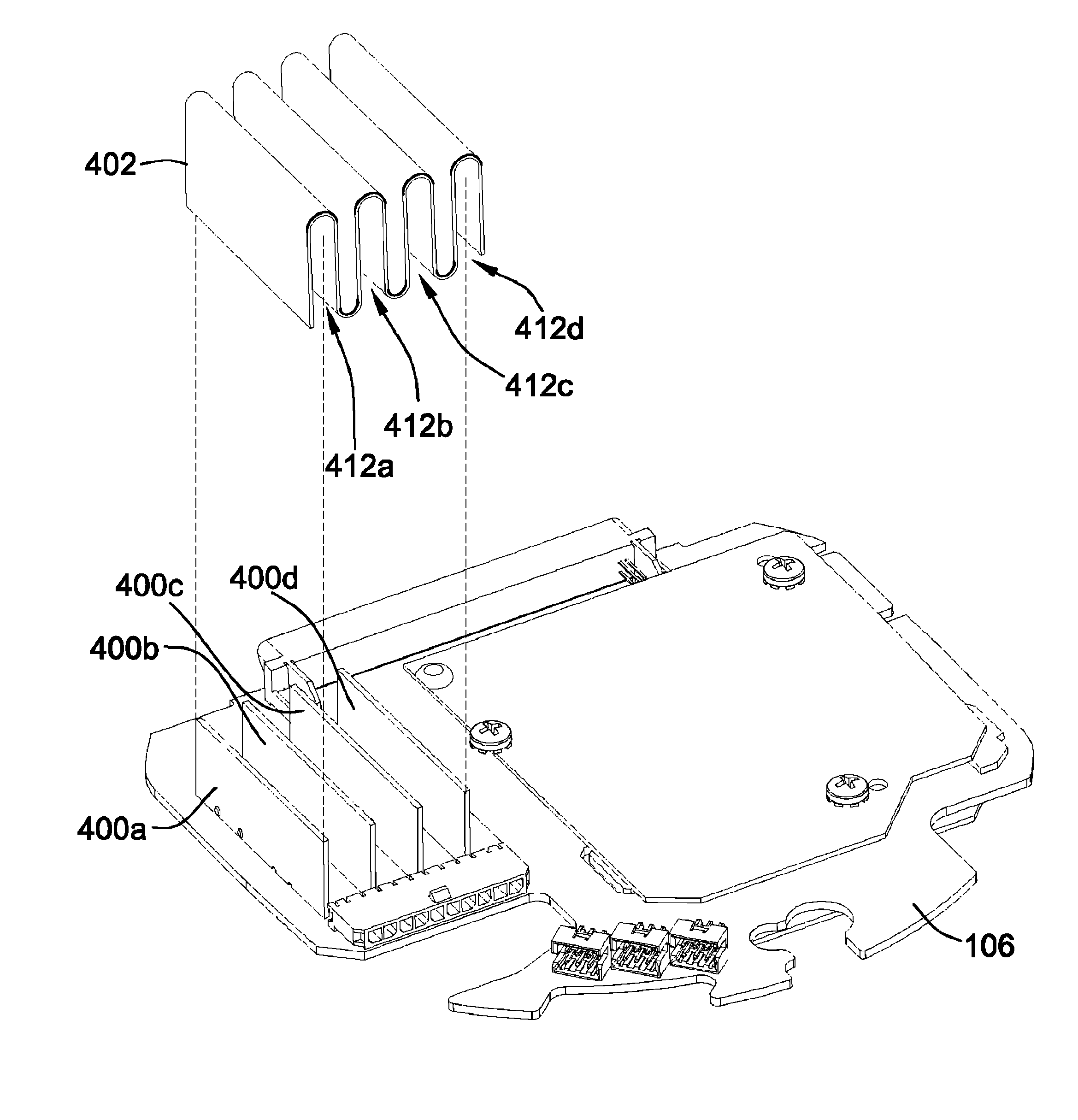
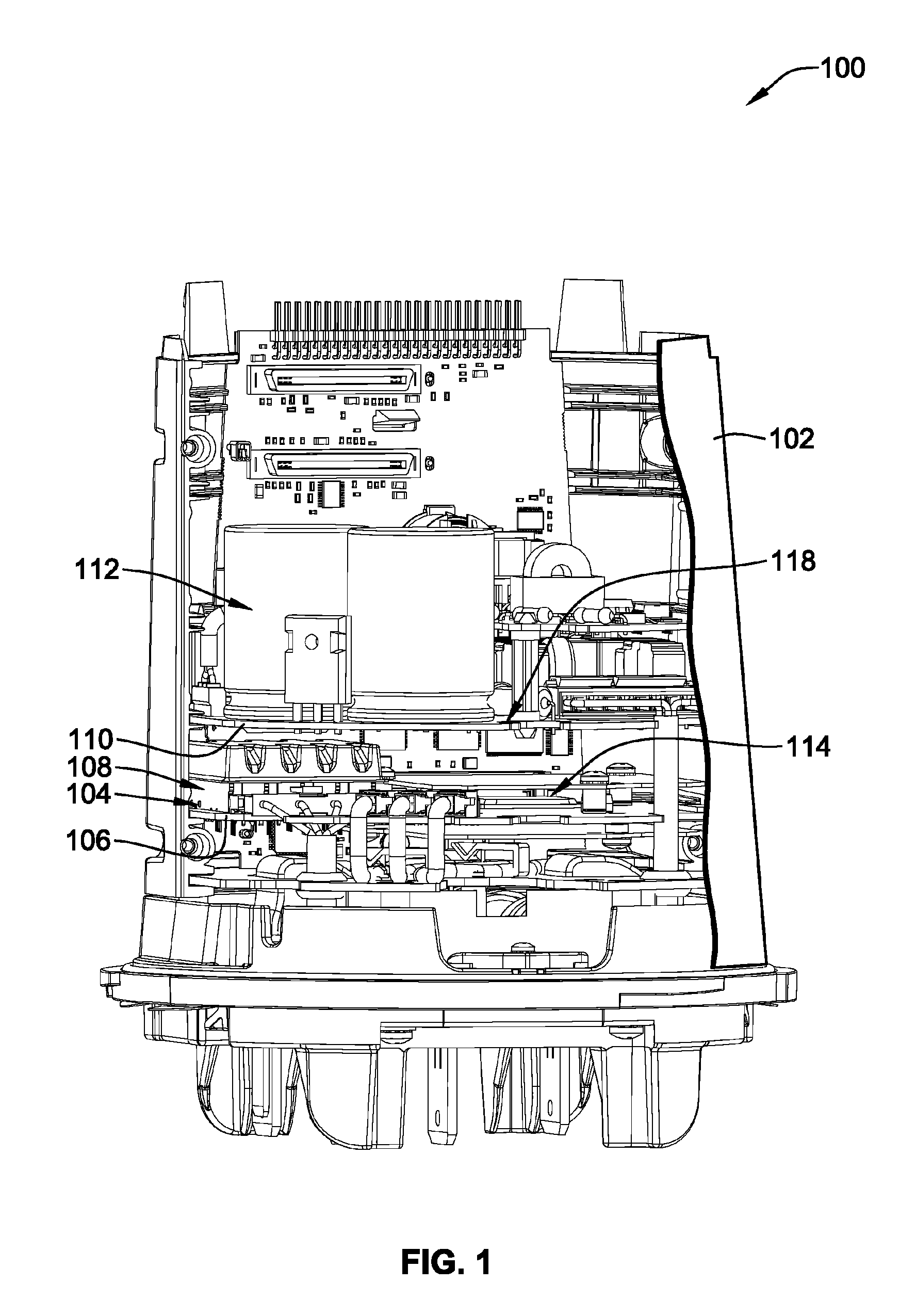
[0018]FIG. 1 is an illustration of a power meter 100 with part of its housing 102 removed to reveal electronic components within the housing 102. A printed circuit board assembly 104 is shown within the housing 102. The printed circuit board assembly 104 includes a main printed circuit board (PCB) 106 and a PCB shield assembly 108. A second circuit board 110 within the housing 102 includes a power supply 112, which powers electronic components 114 on the main PCB 106. The power supply 112 is arranged within the housing 102 in a stacked relationship relative to the main PCB 106. A major flat surface 118 of the second PCB 110 is parallel to a major flat surface 116 (see FIG. 3A) of the main PCB 106, as can be seen in FIG. 1. In this stacked configuration, the field lines of electromagnetic energy produced by high-power components in the power supply 112, which conventionally includes capacitors, transformers, and rectifiers, will tend to emanate away from the power supply 112 and then...


PUM


Abstract

A shield that protects high-value input resistors in a power meter against unwanted effects due to electromagnetic interference from a nearby power supply and / or due to crosstalk from adjacent phases. The shield includes multiple printed circuit board shields that are arranged between each of the input resistors on a main printed circuit board in the power meter. Each PCB shield has a conductive layer that provides the shielding against unwanted energy. The resistors are arranged in a diagonal or parallel manner between each pair of PCB shields to prevent the resistor from movement, which prevents pin fatigue and fixes the value of the parasitic capacitance that is produced in the resistor-PCB-shield combination. In another configuration, the PCB shield is made of a flexible material, and snakes between and over the top or around the side ends of each resistor in a serpentine fashion, protecting the resistors from unwanted energies from both the top and the sides. The PCB shields disclosed herein eliminate variations in the percent error of the measurement phases, which contributes to achieving a highly accurate meter with an overall accuracy of less than 0.1%.

Description

FIELD OF THE INVENTION[0001]The present disclosure relates generally to electronic component shielding, and, more particularly, to a printed circuit board shield assembly to shield resistors against crosstalk and interference due to electromagnetic energy produced by nearby electronic components.BACKGROUND[0002]In a compact power meter, the power supply components include large capacitors, transformers, and other electronic components for converting the high-power inputs to the power meter into smaller voltages sufficient to power the sensitive electronics within the power meter. These power supply components can generate a significant amount of interference in the form of electromagnetic energy. This electromagnetic interference or EMI can adversely affect the performance of other circuits located near the power supply. Moreover, in power meters that receive multiple phases of voltage or current, the inputs are typically located right next to each other and are susceptible to cross...

Claims


Application Information

Patent Timeline
Patent Type & Authority Patents(United States)
IPC IPC(8): H05K7/14H05K7/18
CPCH05K1/0218G01R22/065H05K9/0022H05K3/303Y02P70/50
Inventor RICCI, MARC A.KNOLL, JONATHAN
Owner SCHNEIDER ELECTRIC USA INC
Why Eureka
Try Eureka