
Method for determining a noise reference signal for noise compensation and/or noise reduction

a noise reference signal and noise compensation technology, applied in the direction of instruments, electrical transducers, sound producing devices, etc., can solve the problems of impaired noise reference signal, voice signal interference, and often impaired audio signal quality, so as to reduce noise and minimize the noise component of the first audio signal

Active Publication Date: 2013-02-12
CERENCE OPERATING CO
View PDF4 Cites 74 Cited by
  • Summary
  • Abstract
  • Description
  • Claims
  • Application Information

AI Technical Summary

Benefits of technology

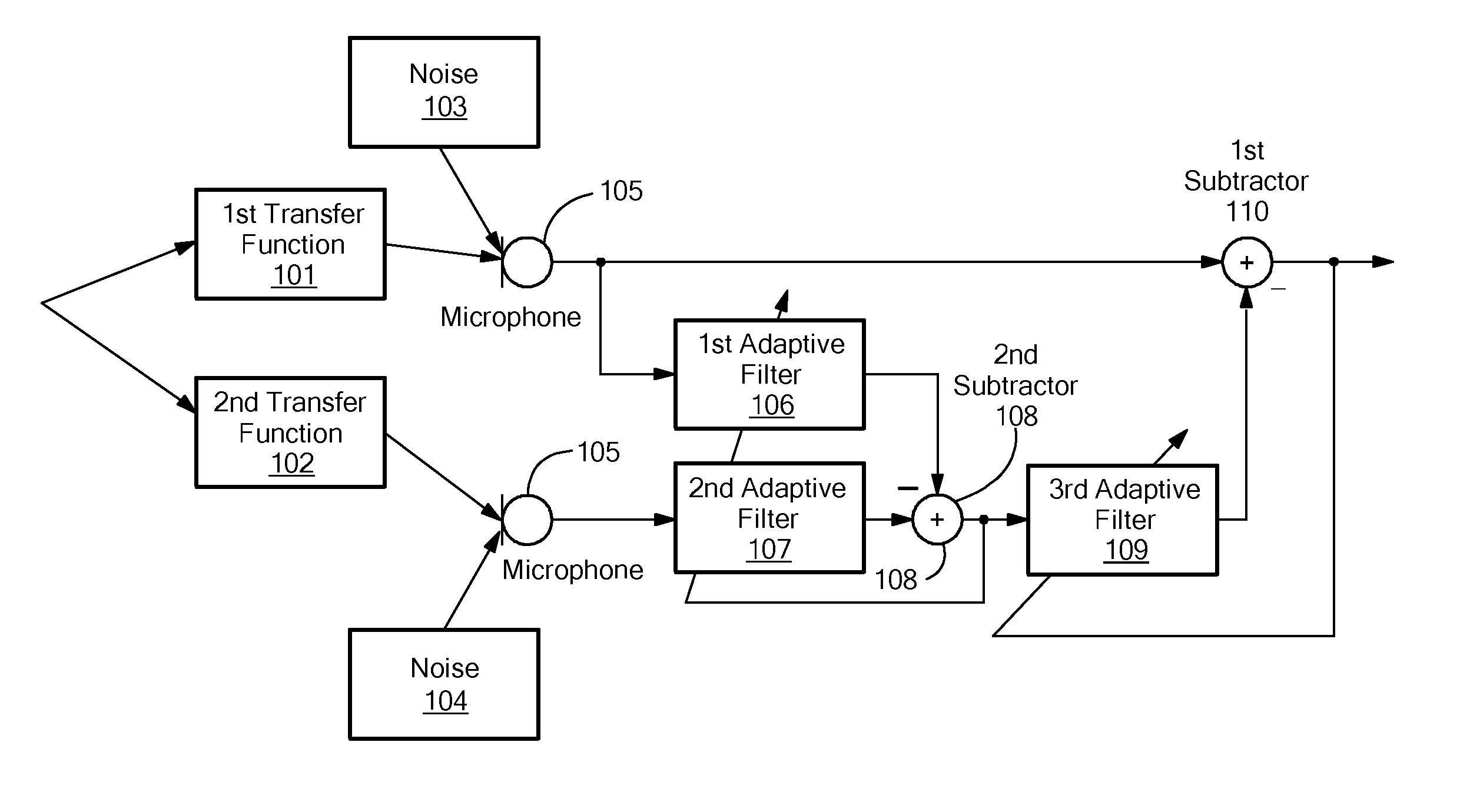
The patent describes a method for improving the quality of a noise reference signal by using two adaptive filters. The first filter minimizes a wanted signal component in the noise reference signal, while the second filter minimizes a noise component. This allows for a better noise reference signal that can be used to improve the quality of an output signal with reduced noise. Ultimately, this results in a higher quality output signal.

Problems solved by technology

The quality of an audio signal, e.g. of a speech signal, is often impaired by various interferences stemming from different noise sources.
In this case, the voice signal may be interfered by background noise such as noise of the engine or noise of the rolling tires.
This can yield an impaired noise reference signal if the value of the first transfer function approaches zero.
Depending on the frequency of the sound, the phase difference may either lead to constructive or destructive interference.
Destructive interference can cause the signal to be destroyed at a particular frequency.

Method used


Image

  • Method for determining a noise reference signal for noise compensation and/or noise reduction
  • Method for determining a noise reference signal for noise compensation and/or noise reduction
  • Method for determining a noise reference signal for noise compensation and/or noise reduction

Examples


Embodiment Construction

[0092]To improve the signal quality of an audio signal, a method for noise compensation may be performed (see e.g. “Adaptive noise cancellation: Principles and applications” by B. Widrow et al., in Proc. of the IEEE, Vol. 63, No. 12, December 1975, pp. 1692-1716). In particular, the audio signal may be divided into sub-bands by some sub-band filter and a noise compensation method may be applied to each of the sub-bands. The method for noise compensation may utilize a multi-channel system, i.e. a system comprising a microphone array. Microphone arrays are also used in the field of source localization (see e.g. “Microphone Arrays for Video Camera Steering” by Y. Huang et al., in S. Gay, J. Benesty (Eds.), Acoustic Signal Processing for Telecommunication, Kluwer, Boston, 2000, pp. 239-259).

[0093]FIG. 4 shows the general structure of a so-called “general sidelobe canceller” which comprises two signal processing paths: a first (or lower) adaptive signal path with a blocking matrix 412 an...


PUM


Abstract

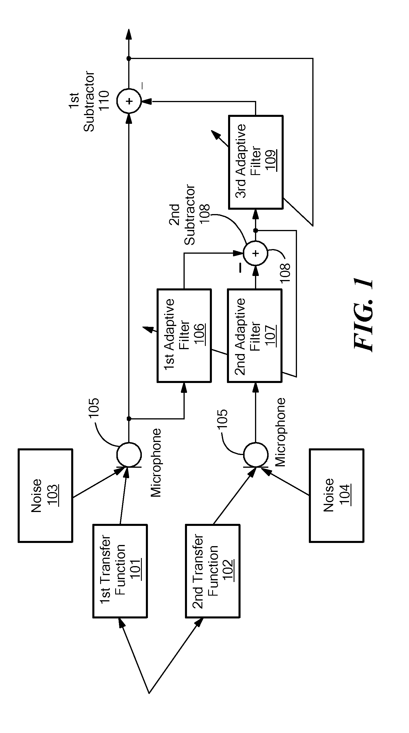
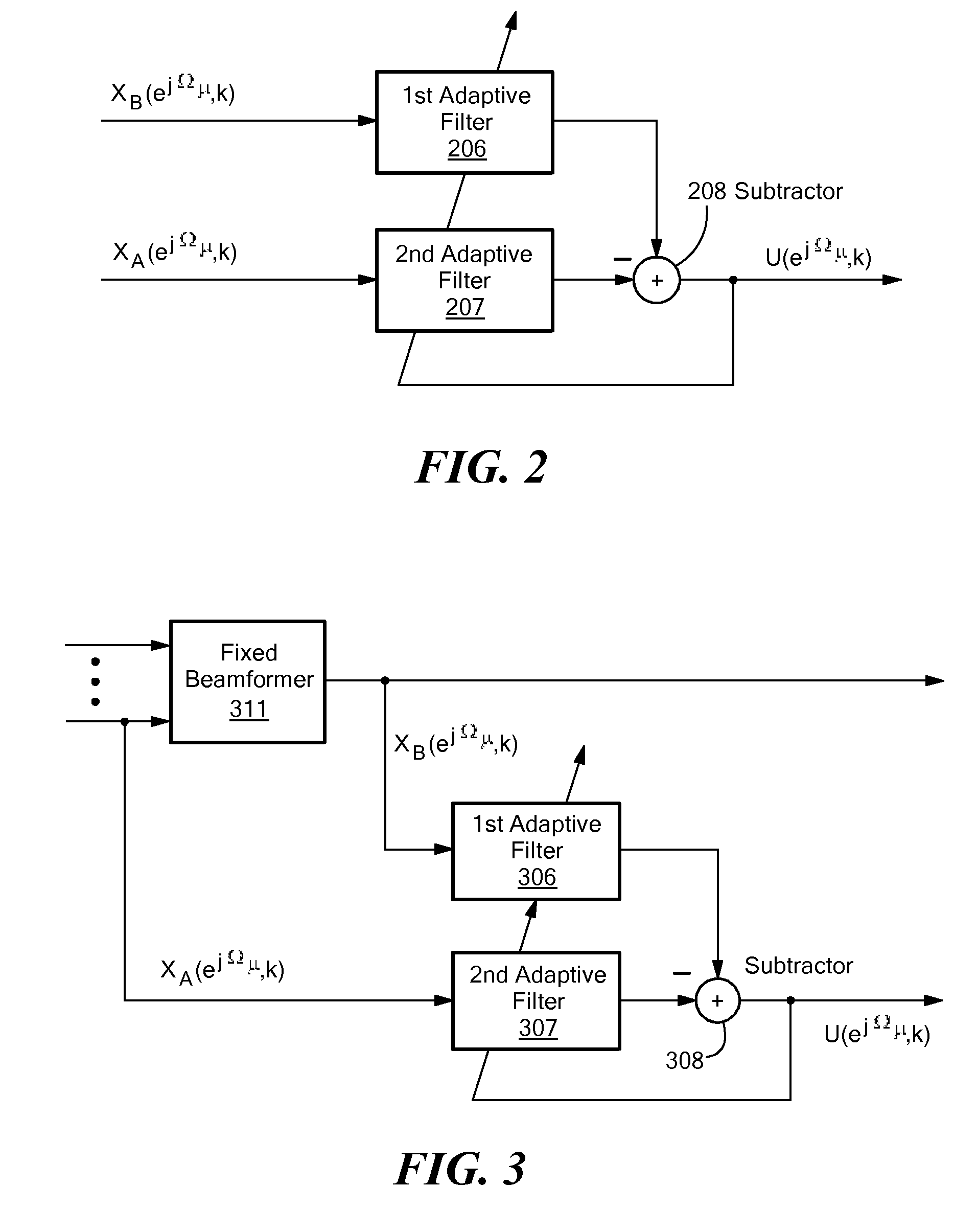
The invention provides a method for determining a noise reference signal for noise compensation and / or noise reduction. A first audio signal on a first signal path and a second audio signal on a second signal path are received. The first audio signal is filtered using a first adaptive filter to obtain a first filtered audio signal. The second audio signal is filtered using a second adaptive filter to obtain a second filtered audio signal. The first and the second filtered audio signal are combined to obtain the noise reference signal. The first and the second adaptive filter are adapted such as to minimize a wanted signal component in the noise reference signal.

Description

PRIORITY[0001]The present U.S. patent application claims priority form European Patent Application No. 09004609.5 filed on Mar. 30, 2009 entitled “A Method for Determining a Noise Reference Signal for Noise Compensation and / or Noise Reduction” which is incorporated herein by reference in its entirety.TECHNICAL FIELD[0002]The present invention relates to a method for determining a noise reference signal for noise compensation and / or noise reduction.BACKGROUND ART[0003]Noise compensation and / or noise reduction in acoustic signals is an important issue, for example, in the field of speech signal processing. The quality of an audio signal, e.g. of a speech signal, is often impaired by various interferences stemming from different noise sources. Hands-free telephony systems or speech recognition systems, for instance, may be used in a noisy environment such as in a vehicular cabin. In this case, the voice signal may be interfered by background noise such as noise of the engine or noise o...

Claims


Application Information

Patent Timeline
Patent Type & Authority Patents(United States)
IPC IPC(8): H04B15/00H04R3/00G10L21/02G10L21/0208G10L21/0216
CPCG10L21/0208G10K11/002G10L2021/02165G10L2021/02166H04R3/005H04R2499/13
Inventor BUCK, MARKUSWOLFF, TOBIASLAWIN-ORE, TOBY CHRISTIANMBOUNGUENG, SAMUEL NGOUOKOSCHMIDT, GERHARD
Owner CERENCE OPERATING CO
Learn More