Pad retraction device

a technology of retraction device and pad, which is applied in the direction of slack adjuster, braking member, braking element, etc., can solve the problems of reducing the air gap, so as to maximize the air gap

Inactive Publication Date: 2013-02-19
AKEBONO BRAKE
View PDF53 Cites 19 Cited by
  • Summary
  • Abstract
  • Description
  • Claims
  • Application Information

AI Technical Summary

Benefits of technology

[0009]Yet another possible embodiment of the present invention includes: a method of preventing drag comprising: contacting a pair of brake pads with a pad retraction device, wherein the pad retraction device comprises: a pair of opposing legs; a bridge between and connecting the pair of legs; a pair of retraction spring arms attached to the outside of each of the legs; the retraction spring arms each comprising: a guide support tab connected to each of the pair of opposing legs wherein the retraction spring arms assist in retracting a pair of brake pads, and the guide support tabs guide the retraction spring arms during movement.
[0010]One unique aspect of the present invention envisions a pad clip that includes at least two unitary retraction arms. The retraction arms are located on the outside of the pad clip so that contact with the brake rotor is minimized and preferably eliminated. The present invention will also allow for a smaller rotor gap so that virtually any rotor (i.e., thickness) may be used, and during a brake apply the pedal travel will be kept short and the brakes will not feel soft. Further, the arms are coplanar so that the force exerted axially by each arm will be substantially the same so that risk of tying and / or tipping of the brake pads is substantially reduced, eliminated, or both.
[0012]Another unique aspect of the present invention envisions each arm including a pull-back feature (i.e. a pull-back curve, a pull-back limb, or both) so that during a brake apply, a brake retract, brake wear, or a combination thereof the retraction arm is not moved into contact with the brake rotor. The pull-back feature further allows for a longer lever arm so that more force is applied, the force is stored in more than one region of the retraction arm, a more consistent force is applied, or a combination thereof.
[0013]Yet another unique aspect of the present invention envisions a unitary locator that enables the pad clip to be fixedly attached to the support bracket and allows for some axial movement of the entire pad clip, relative to the rotor. The locator of the present invention has some springing properties so that pad clip may move axially by a force applied to the pad clip. The springing properties allow to the pad clip to reposition itself if the pad clip is improperly attached or the pad clip is axially moved away from the desired location. Accordingly, it has been identified by the present inventor that it is important to employ a particular design for pad clips that include retraction arms so that the brake pads can be retracted and the air gap maximized without damaging the rotor, the pad clip, or both; the pad clip providing inconsistent retraction; creating noise, vibration or harshness; or a combination thereof.

Problems solved by technology

One disadvantage faced by pad clips that include retraction arms (hereinafter pad clip) is that the retraction arms are located in the center of the pad clip.
Thus, the rotor and the retraction arms are located in the same gap, and the retraction arms may contact the rotor or vice versa potentially damaging the rotor, the pad clip, or both.
The retraction arms may further contact the rotor causing brake noise, vibration, harshness, or a combination thereof.
Another disadvantage is that the addition of the one or more retraction arms into the rotor gap reduces the amount of space available on either side of the rotor or requires a larger rotor gap so that the pad clip does not contact the rotor.
In order to compensate for the reduction of space in the rotor gap due to the retraction arms, the support bracket may require expensive design changes so that a consistent gap may be maintained between the rotor and the pad clip / support bracket.
Another disadvantage faced by pad clips is that the retraction arms are staggered or offset (i.e. not located on the same plane).
This may cause an unequal force to be applied on the opposing brake pads.
It may also cause tying and / or tipping of the brake pads due to opposing ends of the brake pads being contacted at different locations or heights.
Yet another disadvantage faced by pad clips is that the length of the retraction arms are short due to the arms being located in the center of the pad clip.

Method used


Image

  • Pad retraction device
  • Pad retraction device
  • Pad retraction device

Examples


Embodiment Construction

[0019]The following description of the preferred embodiment(s) is merely exemplary in nature and is in no way intended to limit the invention, its application, or uses.

[0020]The present invention is predicated upon providing an improved brake assembly for use with vehicles. For example, the brake assembly may be used with almost any vehicle (e.g. car, truck, bus, train, airplane, or the like). Alternatively, the brake assembly may be integrated into components used for manufacturing or other equipment that require a brake such as a lathe, winder for paper products or cloth, amusement park rides, or the like. However, the present invention is most suitable for use with a passenger vehicle (i.e. a car, truck, sports utility vehicle, or the like).

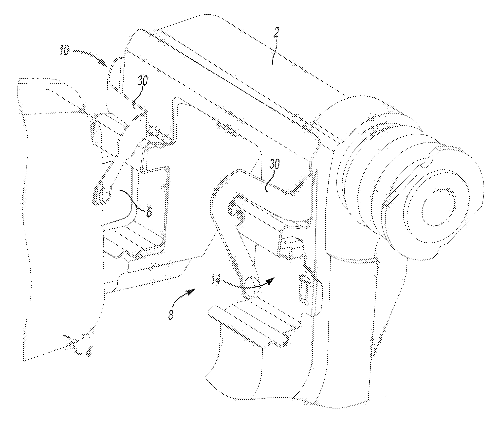
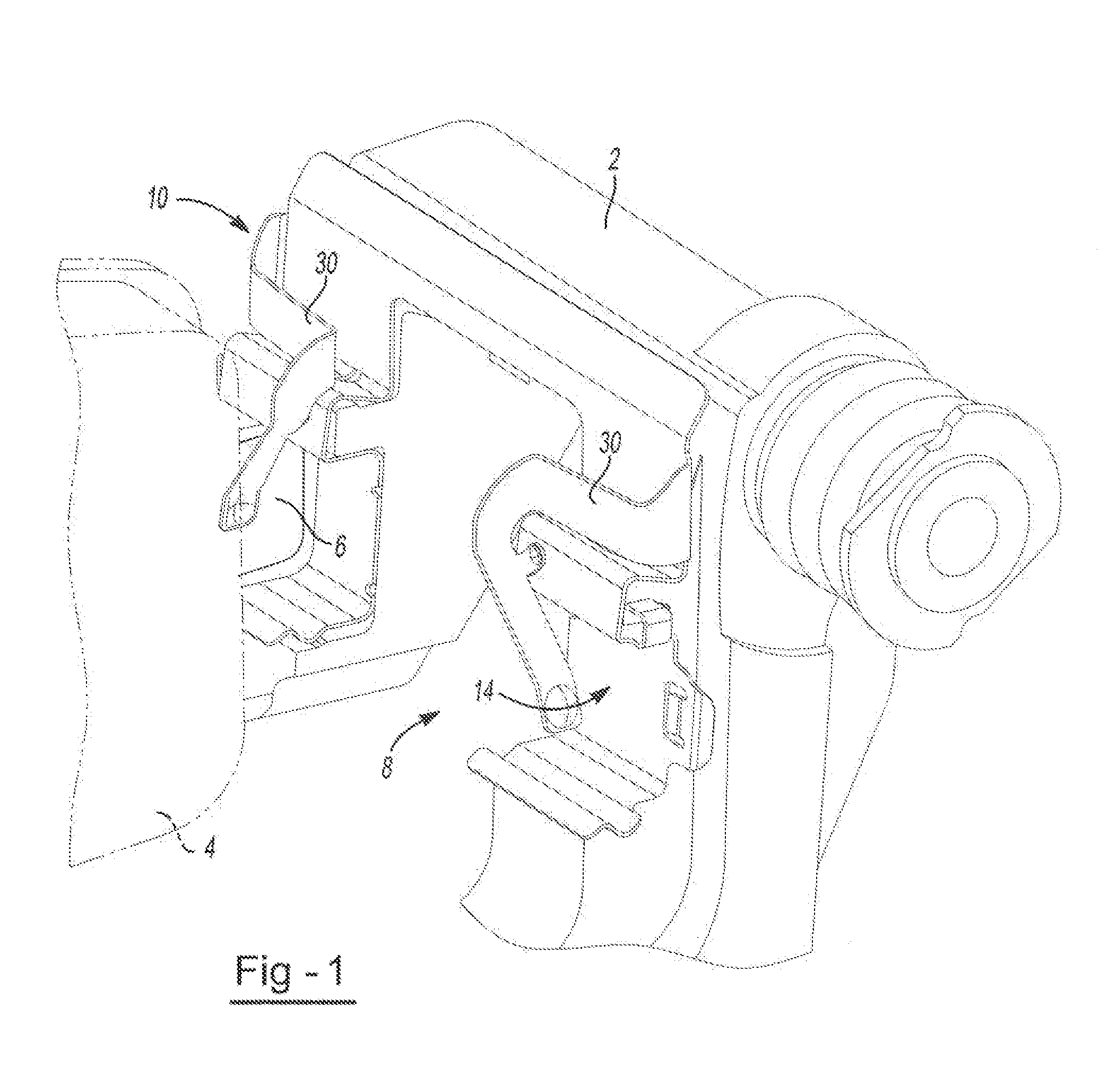
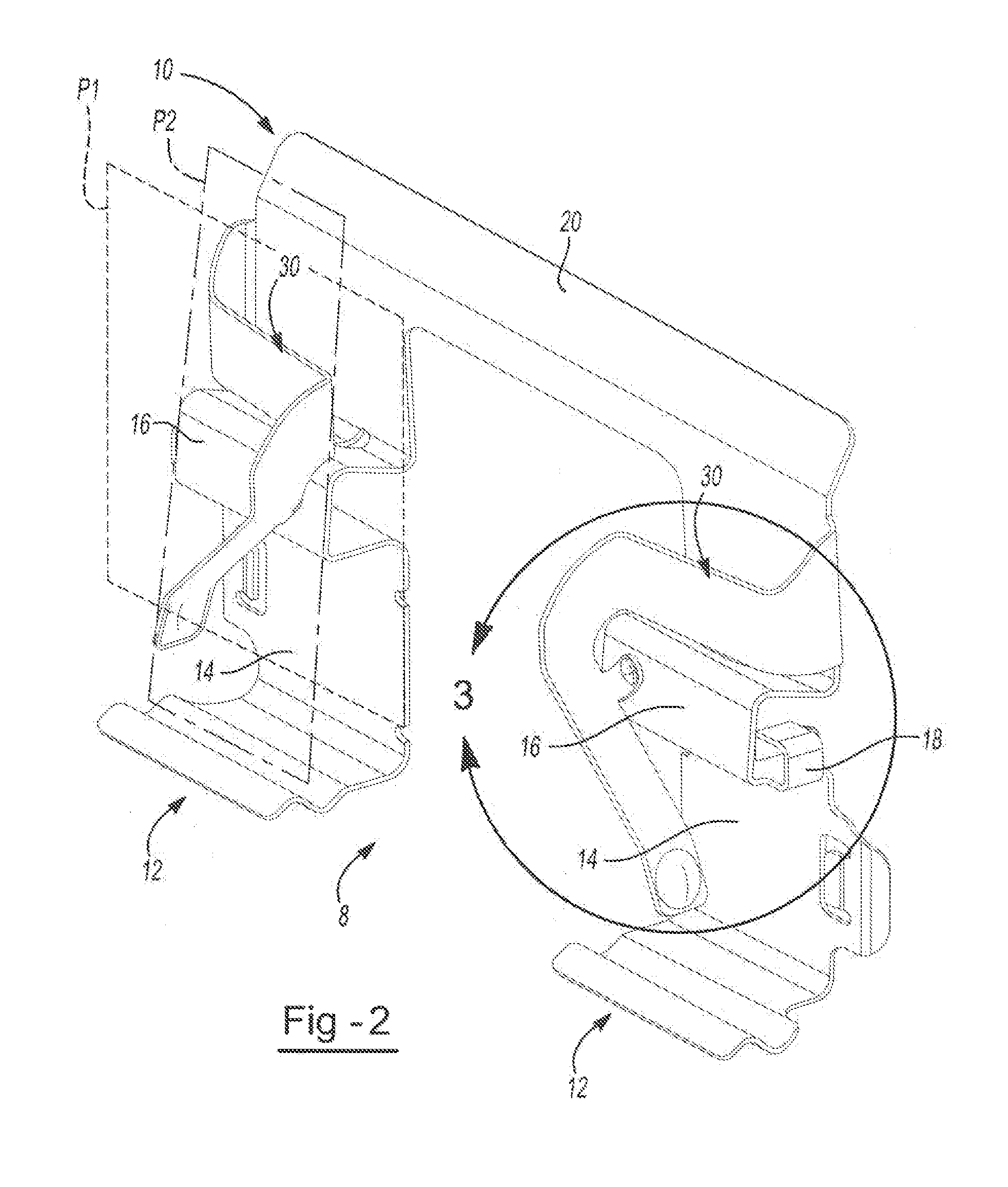
[0021]Generally, a brake assembly includes a caliper body, a rotor, and two brake pads. The caliper body is in communication with an inboard brake pad and an outboard brake pad that are on opposing sides of the rotor. The brake pads may be hel...


PUM


Abstract

A device comprising: a pair of opposing legs; a bridge between and connecting the pair of legs; a pair of retraction spring arms attached to the outside of each of the legs; the retraction spring arms each comprising: a guide support tab connected to each of the pair of opposing legs wherein the retraction spring arms assist in retracting a pair of brake pads, and the guide support tabs guide the retraction spring arms during movement.

Description

FIELD OF THE INVENTION[0001]The present invention generally relates to a brake system and more particularly a pad clip that assists in retracting the brake pads.BACKGROUND OF THE INVENTION[0002]Typical, disc brake systems include a support bracket, two more brake pads, a caliper, and a rotor. The at least two brake pads are mounted and located adjacent to the support bracket so that the brake pads move axially towards and away from the rotor. The disc brake system may include a pad clip that attaches to the support bracket and to a portion of the one or more brake pads so that the brake pads are held by the support bracket. The disc brake system may include one or more springs that attach to the brake pads to assist in retracting the brake pads. However, in some instances pad clips may include arms that assist in retraction instead of adding a separate spring. The addition of one or more clips that include retraction arms may require modifications to be made to the support bracket, ...

Claims


Application Information

Patent Timeline
Patent Type & Authority Patents(United States)
IPC IPC(8): F16D55/22
CPCF16D65/0972F16D65/0977
Inventor LETHORN, BRAD ROBERT
Owner AKEBONO BRAKE
Why Eureka
Try Eureka