Drill, a drill assembly, and a tool head for a cutting tool

a technology for drilling tools and cutting tools, applied in the field of drilling tools, can solve the problems of weakened drilling members, resilient expansion of the driving tangs of the drilling members, and problems with the evacuation of chips

Active Publication Date: 2013-02-19
KENNAMETAL INC
View PDF29 Cites 29 Cited by
  • Summary
  • Abstract
  • Description
  • Claims
  • Application Information

AI Technical Summary

Benefits of technology

[0009]The task is solved according to at least one possible embodiment of a drilling tool disclosed herein. In accordance with at least one possible embodiment, the drilling tool comprises a drilling member and a tool head exchangeably fixed thereon by means of a driving connector formed on the front-face end, the driving connector being formed by a driving web, arranged in at least one embodiment on the tool head on the latter's end face facing towards the drilling member, as well as by a receiving pocket formed on the front-face end of the drilling member and including a peripheral web for receiving the driving web along its complete periphery. Therefore, on the end face of the drilling member, there is a peripheral web, formed, for example, in the manner of an oval, which completely surrounds the driving web in the manner of a pocket. This measure minimizes or restricts the formation of two separate driving tangs on the drilling member. Due to the peripheral design of the web, the torques to be transmitted are completely led into the peripheral web, without the risk of a resilient expansion of the driving adaptor.SUMMARY
[0010]According to at least one possible embodiment, the driving web is surrounded by a contact face extending along the complete periphery and tightly resting on a corresponding contact face of the base body, extending along the periphery of the receiving pocket. The contact face is plane and extends normal to the axial direction. Alternatively to the plane design, the contact face is curved, for example in the manner of an envelope of cone. Therefore, the driving web is designed altogether corresponding to the receiving pocket and extends essentially only or substantially only over a partial area of the diameter. The fact that, in operation, the contact faces of the drilling member and of the tool head tightly rest on each other promotes a gap-free axial seating of the drill head on the drilling member. This reduces, on the one hand, the risk of problems of chip evacuation. On the other hand, the tight plane seating enables the introduction of coolant from the drilling member into the tool head through corresponding coolant channels passing through the contact faces.
[0011]According to at least one possible embodiment, the width of the driving web increases in direction towards its margin areas. Therefore, the web width is smallest in the drilling center, so that the core cross-section of the drilling-member adaptor is weakened very little. At the same time, there is sufficient space in the drilling center for the design of the peripheral web of the receiving pocket. At the same time, the increase of the width in direction towards the margin areas of the driving web, spaced from the drilling center, results in the driving web being reinforced in the areas in which the high torques have to be transmitted. Another advantage of the increasing web width lies in the fact that this measure provides a radial centering.
[0013]According to another possible embodiment, the tool head is fixed on the drilling member by screws oriented in axial direction. Therefore, the peripheral web of the receiving pocket is not weakened through radially arranged screws. According to at least one possible embodiment, the screws are passed through margin areas of the driving web spaced from the drilling center and screwed into a pocket bottom of the receiving pocket. As the screws are passed through the thicker margin areas and are, furthermore, screwed into the pocket bottom at a distance from the core cross-section, both the weakening of the driving web and the weakening of the drilling-member adaptor is low and has been shifted to uncritical areas.
[0016]To promote a seating of the driving web in the receiving pocket with optimum fit, the driving web has in at least one possible embodiment an overmeasure relative to the receiving pocket, at least in partial areas. Insertion bevels are provided on each end face for the installation. The overmeasure causes a slight resilient expansion of the peripheral web of the receiving pocket, so that the driving web is also held in the receiving pocket by friction, forming a press fit. Alternatively thereto, it is possible to provide an installation play relative to the receiving pocket, to enable a relatively easy installation of the tool head in the drilling member.
[0019]The object may further be solved according to at least one possible embodiment of a tool head for such a drilling tool as described herein. The advantages and possible embodiments mentioned with regard to the drilling tool can analogously also be applied to the tool head. The tool head includes in at least one possible embodiment a central drill-point insert and exchangeable cutting inserts, such as indexable inserts, arranged on both sides thereof. A drilling head of such a design is cost-advantageous in operation, due to the use of the exchangeable cutting inserts and allows very high cutting speed as well as a high feed rate.

Problems solved by technology

The high torques entail the risk that the driving tangs on the drilling member are resiliently expanded.
Due to the radially oriented securing screws, there is an axial gap between the drilling member and the drilling head, which in operation may cause problems with the evacuation of the chips.
In addition, the drilling member is weakened by the radial securing screws passed through the driving tangs.
Finally, the centering pin arranged in the center weakens the core cross-section of the drilling-member adaptor.
As the screws are passed through the thicker margin areas and are, furthermore, screwed into the pocket bottom at a distance from the core cross-section, both the weakening of the driving web and the weakening of the drilling-member adaptor is low and has been shifted to uncritical areas.

Method used


Image

  • Drill, a drill assembly, and a tool head for a cutting tool
  • Drill, a drill assembly, and a tool head for a cutting tool
  • Drill, a drill assembly, and a tool head for a cutting tool

Examples


Embodiment Construction

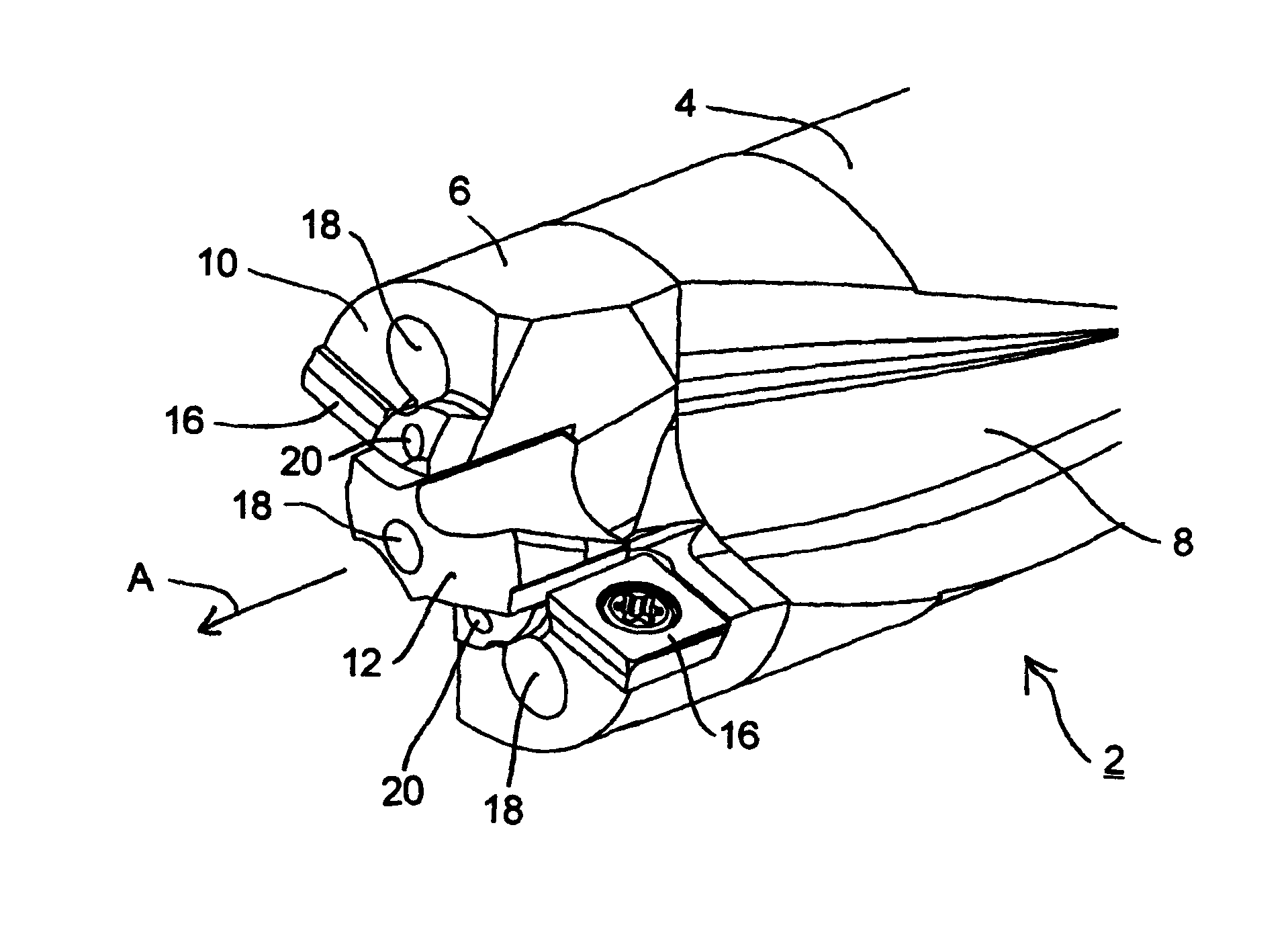
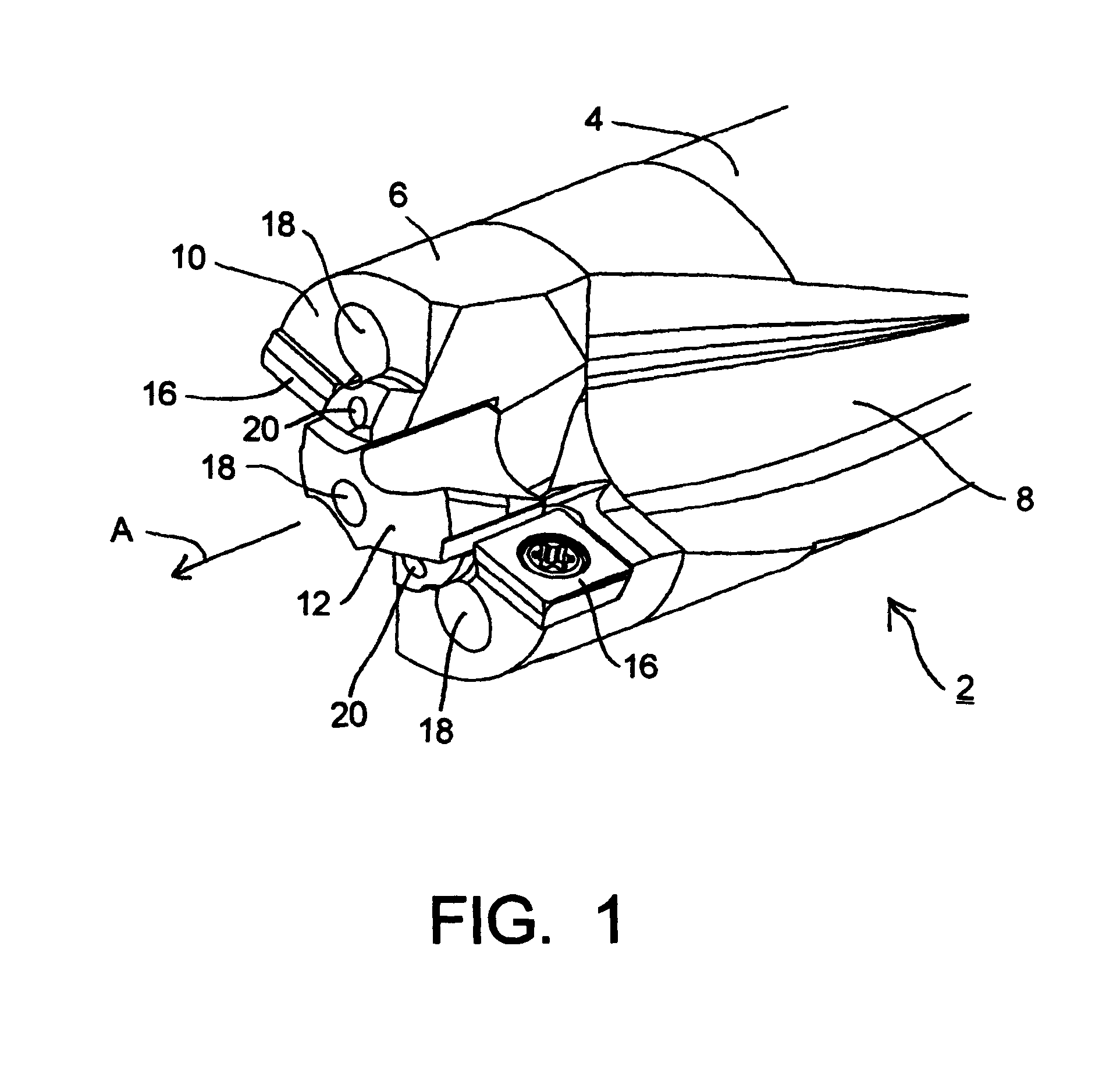
[0028]The drilling tool 2 extending in axial direction A according to FIG. 1 comprises a drilling member 4, on the front end face of which a drilling head 6 is exchangeably fixed. What is meant by drilling member 4 is in general the partial area of the tool, which during the machining operation usually engages the workpiece to be machined at least still in part, serving, for example, for chip evacuation or also performing a cutting function. In the embodiment shown, the drilling member 4 includes two helical flutes 8 arranged opposite each other, for chip evacuation. These chip flutes verge smoothly into opposite flute areas of the drilling head 6. On its rear end, not shown here in detail, the drilling member 4 has a clamping shank with which it can be clamped in a machine tool.

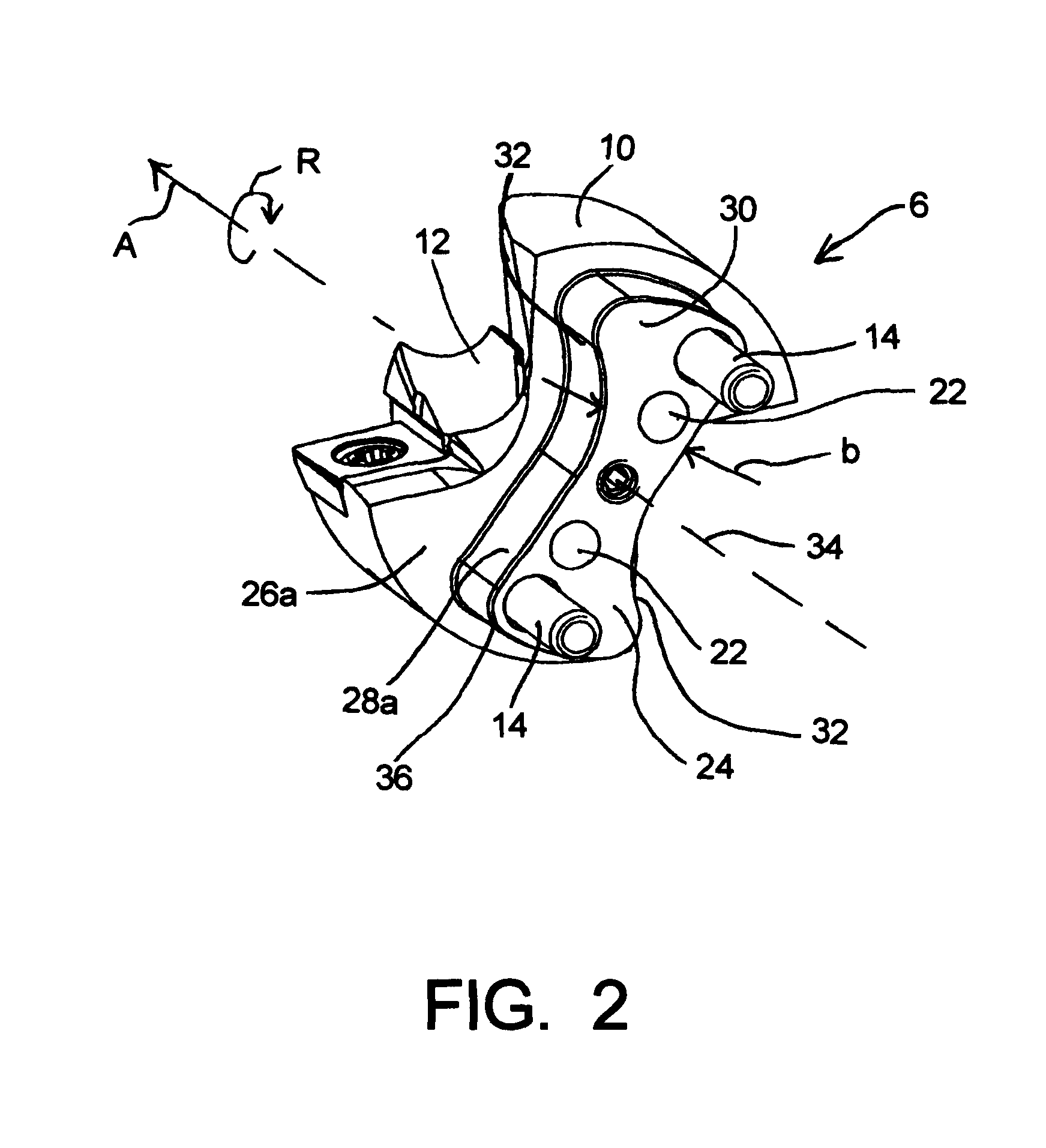
[0029]The drilling head 6 is of a multipiece design and includes a base body 10, in the center of which a drill-point insert 12 is exchangeably fixed by means of a screw. The drill-point insert 12 constitute...


PUM

PropertyMeasurementUnit
widthaaaaaaaaaa
diameteraaaaaaaaaa
torquesaaaaaaaaaa

Abstract

A drill includes a tool body having a fluted portion having a second end and a tool head portion, having a cutting tip and at least one cutting edge, removably connected to the second end of the fluted portion. The fluted portion includes a receiving pocket disposed in the second end and is defined by a peripheral side wall extending about the periphery of the receiving pocket. The tool head portion includes a driving projection configured to be inserted into the receiving pocket. The driving projection and receiving pocket have corresponding elongated, curvilinear, dog-bone shapes. The driving projection includes a first end portion, a second end portion, and a central portion disposed between connecting the first end portion and the second end portion. The first end portion and the second end portion each have a width that is substantially greater than a width of the central portion.

Description

CONTINUING APPLICATION DATA[0001]This application is a Continuation-In-Part application of International Patent Application No. PCT / 2007 / 002313, filed on Mar. 16, 2007, which claims priority from Federal Republic of Germany Patent Application No. 10 2006 012 382.4, filed on Mar. 17, 2006. International Patent Application No. PCT / 2007 / 002313 was pending as of the filing date of this application. The United States was an elected state in International Patent Application No. PCT / 2007 / 002313.BACKGROUND[0002]1. Technical Field[0003]This application relates to a drilling tool with a drilling member and a tool head exchangeably fixed thereon by means of a driving connector formed on the front-face end, the driving connector comprising a driving adaptor and a driving web extending over the tool center and engaging the driving adaptor. This application also relates to a tool head for such a drilling tool.[0004]2. Background Information[0005]Background information is for informational purpose...

Claims


Application Information

Patent Timeline
Patent Type & Authority Patents(United States)
IPC IPC(8): B23B51/02
CPCB23B31/11B23B31/113B23B51/02Y10T408/9098B23B2251/14Y10T408/907Y10T408/90993B23B2251/02
Inventor JAEGER, HORST MANFREDMERGENTHALER, PETER KARLZEUG, BERTHOLD HEINRICH
Owner KENNAMETAL INC
Why Eureka
Try Eureka