Variable-capacity exhaust turbocharger equipped with variable-nozzle mechanism

a technology of variable nozzle and exhaust turbocharger, which is applied in the direction of reaction engines, machines/engines, liquid fuel engines, etc., to achieve the effects of increasing the thickness of the lever plate, preventing the occurrence of local excessive stress, and increasing the rigidity of the lever plate withou

Active Publication Date: 2013-02-19
MITSUBISHI HEAVY IND ENGINE & TURBOCHARGER LTD
View PDF12 Cites 13 Cited by
  • Summary
  • Abstract
  • Description
  • Claims
  • Application Information

AI Technical Summary

Benefits of technology

[0024]The present invention is contrived in consideration of the above-described problems, and an object of the invention is to provide a variable-capacity exhaust turbocharger equipped with a variable-nozzle mechanism having a lever plate and a peripheral structure capable of ensuring regular operability of a nozzle vane and of preventing an occurrence of local excessive stress by increasing rigidity of the lever plate without increasing a thickness of the lever plate.

Problems solved by technology

However, the exhaust turbocharger equipped with the variable-nozzle mechanism according to the conventional art shown in FIGS. 7 to 9 still has the following problems to be solved.

Method used


Image

  • Variable-capacity exhaust turbocharger equipped with variable-nozzle mechanism
  • Variable-capacity exhaust turbocharger equipped with variable-nozzle mechanism
  • Variable-capacity exhaust turbocharger equipped with variable-nozzle mechanism

Examples


first embodiment

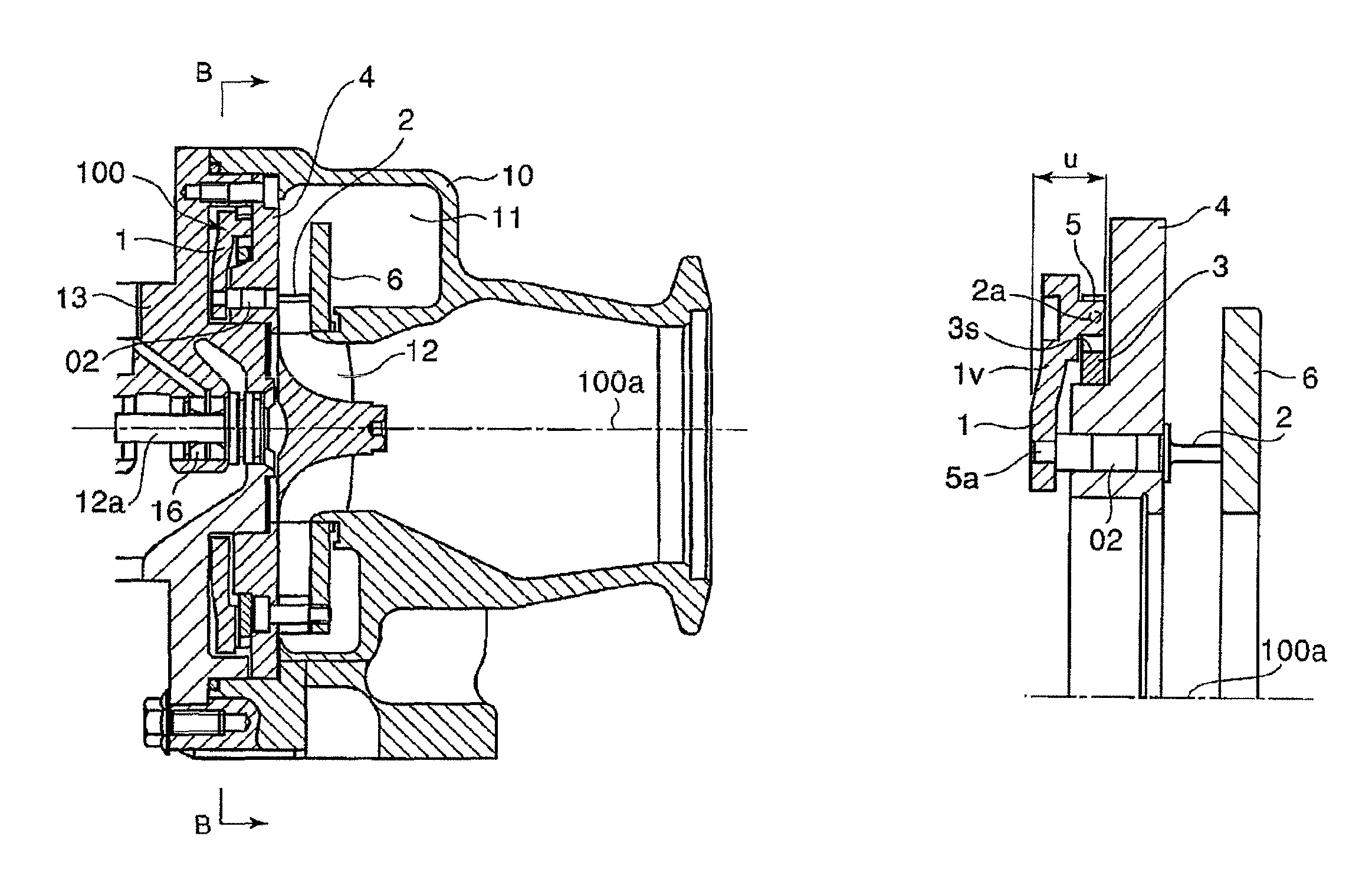
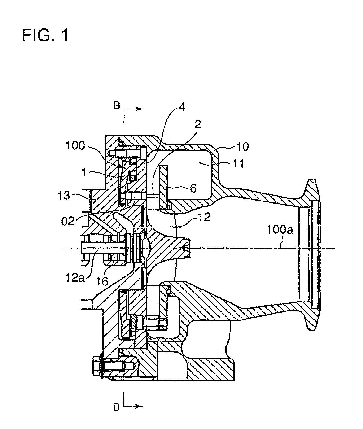
[0057]In FIGS. 1 to 3, Reference Numeral 3 denotes a drive ring formed in a disk shape and rotatably supported to the turbine casing 10. In the same manner as FIG. 7, the crank pin 10s engages with the drive ring 3 so as to rotationally drive the drive ring 3. Here, Reference Numeral 15 denotes a linkage connected to an actuator (not shown) as a driving source of the nozzle vane 2, and Reference Numeral 10s denotes a crank pin connected to the linkage 15.

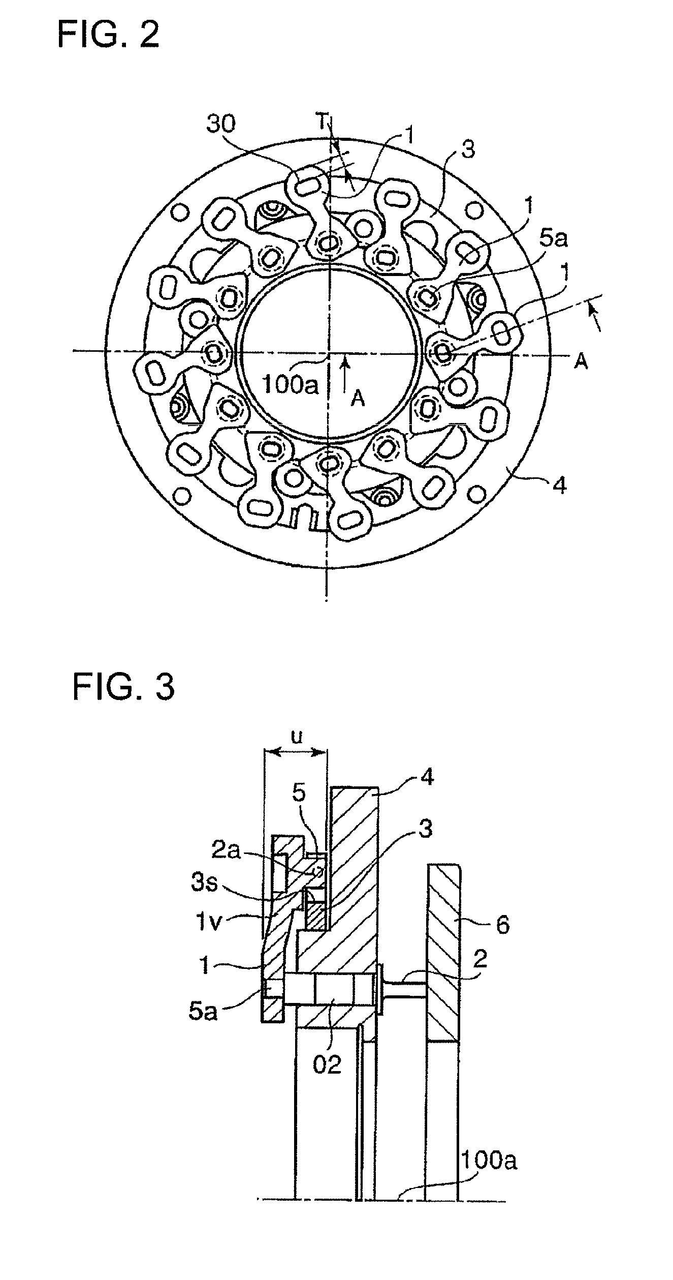
[0058]Additionally, the drive ring 3 is disposed between a lever plate 1 and the nozzle mount 4 in an axial direction.

[0059]A plurality of the lever plates 1 is arranged in a circumferential direction as many as the number of the nozzle vanes 2. A curved portion 1v is curved in an axial direction from the surface of each lever plate 1 connected to the inner-peripheral side as a fixed portion 5a on the side of the nozzle vane 2. In the upper end portion of the curved portion 1v, an engagement protrusion 5 is integrally formed with th...

second embodiment

[0067]FIG. 4 is a sectional view showing a second embodiment and corresponding to FIG. 3.

[0068]In the second embodiment, the engagement pin portion of the lever plate 1 is configured in such a manner that an engagement pin 2s is fitted in a direction perpendicular to a surface 1p of the lever plate 1, and the engagement pin 2s engages with the groove portion 3s of the drive ring 3 to be caulked in a caulking portion 2t. Reference Numeral 1s denotes a curved portion.

[0069]In this case, only the engagement pin 2s is formed of material having higher rigidity, and the lever plate 1 is configured as a low-cost member, thereby reducing a cost.

[0070]The other configurations are the same as those of the first embodiment shown in FIGS. 1 to 3, and the same reference numerals are given to the same components.

third embodiment

[0071]FIG. 5 is a sectional view showing a third embodiment and corresponding to FIG. 3.

[0072]In the third embodiment, the drive ring 3 is disposed between the lever plate 1 and the nozzle mount 4 in an axial direction, and the lever plate 1 is connected to the fixed portion 5a on the side of the nozzle vane. The curved portion 1v curved in an axial direction from a surface 1u of the lever plate 1 and the engagement protrusion 5 connected to the curved portion 1v to engage with the groove portion 3s of the drive ring 3 are formed by bending one sheet of bar-shape plate.

[0073]The other configurations are the same as those of the first embodiment shown in FIGS. 1 to 3, and the same reference numerals are given to the same components.

[0074]According to the third embodiment, since the curved portion 1v and the engagement protrusion 5 are formed by bending one sheet of bar-shape plate, it is possible to form the engagement protrusion 5 for allowing the lever plate 1 to engage with the gr...


PUM


Abstract

A variable-capacity exhaust turbocharger is provided which is equipped with a variable-nozzle mechanism having a lever plate and a peripheral structure capable of ensuring regular operability of a nozzle vane and of preventing an occurrence of local excessive stress by increasing rigidity of the lever plate without increasing a thickness of the lever plate. In a variable-capacity exhaust turbocharger equipped with a variable-nozzle mechanism including: a plurality of nozzle vanes; an annular drive ring; and a lever plate provided as many as the number of the nozzle vanes so that one end is connected to an engagement pin portion engaging with a groove portion formed in the drive ring and the other end is fixed to each nozzle vane, the drive ring is disposed between the lever plate and a nozzle mount in an axial direction, and the lever plate is curved in an axial direction from a surface of the lever plate connected to the fixed portion on the side of the nozzle vane so as to be connected to the groove portion of the drive ring.

Description

BACKGROUND OF THE INVENTION[0001]1. Field of the Invention[0002]The present invention relates to a variable-capacity exhaust turbocharger equipped with a variable-nozzle mechanism which is used for an exhaust turbocharger of an internal-combustion engine and includes a plurality of nozzle vanes rotatably supported to a nozzle mount, a rotational-driven annular drive ring, and a lever plate of which one end engages with the drive ring and another end is fixed to each nozzle vane, where each blade angle of the plurality of nozzle vanes is changed in such a manner that the lever plate is swung by a rotation of the drive ring.[0003]2. Description of the Related Art[0004]Among comparatively small-size exhaust turbochargers used for a vehicle internal-combustion engine or the like, a double-flow-type variable-capacity exhaust turbocharger equipped with a variable-nozzle mechanism is widely used in which exhaust gas discharged from an engine is filled into a scroll formed in a turbine casi...

Claims


Application Information

Patent Timeline
Patent Type & Authority Patents(United States)
IPC IPC(8): F01D17/16
CPCF01D17/165F05D2220/40F02B39/00F02B37/24F02B37/22F01D17/16
Inventor SUZUKI, HIROSHIJINNAI, YASUAKIUENO, YOICHIHAYASHI, NORIYUKI
Owner MITSUBISHI HEAVY IND ENGINE & TURBOCHARGER LTD
Why Eureka
Try Eureka