Convection oven

a convection oven and oven technology, applied in the field of ovens, can solve the problems of not being disposed of in a desirable or efficient manner, conventional ovens do not provide convenient access to electrical components of ovens, and certain types of food products are particularly difficult to cook quickly and uniformly, so as to achieve convenient access

Active Publication Date: 2013-02-19
DUKE MANUFACTURING COMPANY
View PDF105 Cites 104 Cited by
  • Summary
  • Abstract
  • Description
  • Claims
  • Application Information

AI Technical Summary

Benefits of technology

[0009]One aspect of the present invention is directed to a convection oven comprising a cooking chamber for receiving food to be cooked, a blower for circulating gas (e.g., air) through the cooking chamber, a heater for heating the gas, and a housing for housing electrical components of the oven. The housing comprises front, back and side walls. The front wall is movable from a first position in which the electrical components are concealed within the housing to a second position in which the electrical components are exposed. The electrical components are mounted within the housing at positions relative to the front wall such that the electrical components may be conveniently accessed by an operator when the front wall is in the second position. An operator input is provided on the front wall of the housing for inputting information to the electrical control components.

Problems solved by technology

Certain types of food products are especially difficult to cook quickly and uniformly.
For example, conventional ovens do not provide convenient access to electrical components of the ovens for servicing or other purposes.
Further, once disassembly enables access to the electrical components, the components are not mounted within the oven in a position or orientation for convenient servicing.
Another drawback of known ovens is that steam formed during the baking process is not disposed of in a desirable or efficient manner.
Drawbacks also exist in the steam generation systems used to inject water against heated rotating blower wheels to generate steam for the cooking process in existing ovens.
For example, some water injection systems involve atomizers having complex designs in combination with the blower wheel to atomize injected water.
Other water injection systems are simpler, but result in less efficient generation of steam.
Further, in some water injection systems, some of the injected water does not turn to steam and subsequently contacts the product to be cooked (e.g., bread), undesirably affecting the cooking process.
However, such systems often fail to achieve uniform cooking of food in the cooking chamber.

Method used


Image

  • Convection oven
  • Convection oven
  • Convection oven

Examples


Embodiment Construction

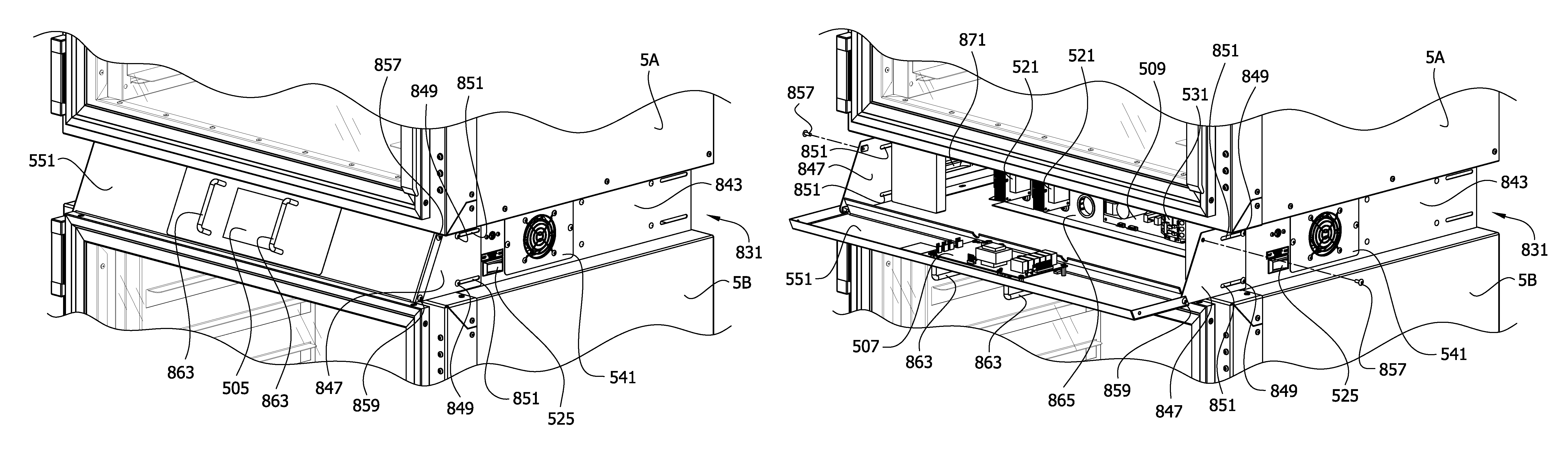
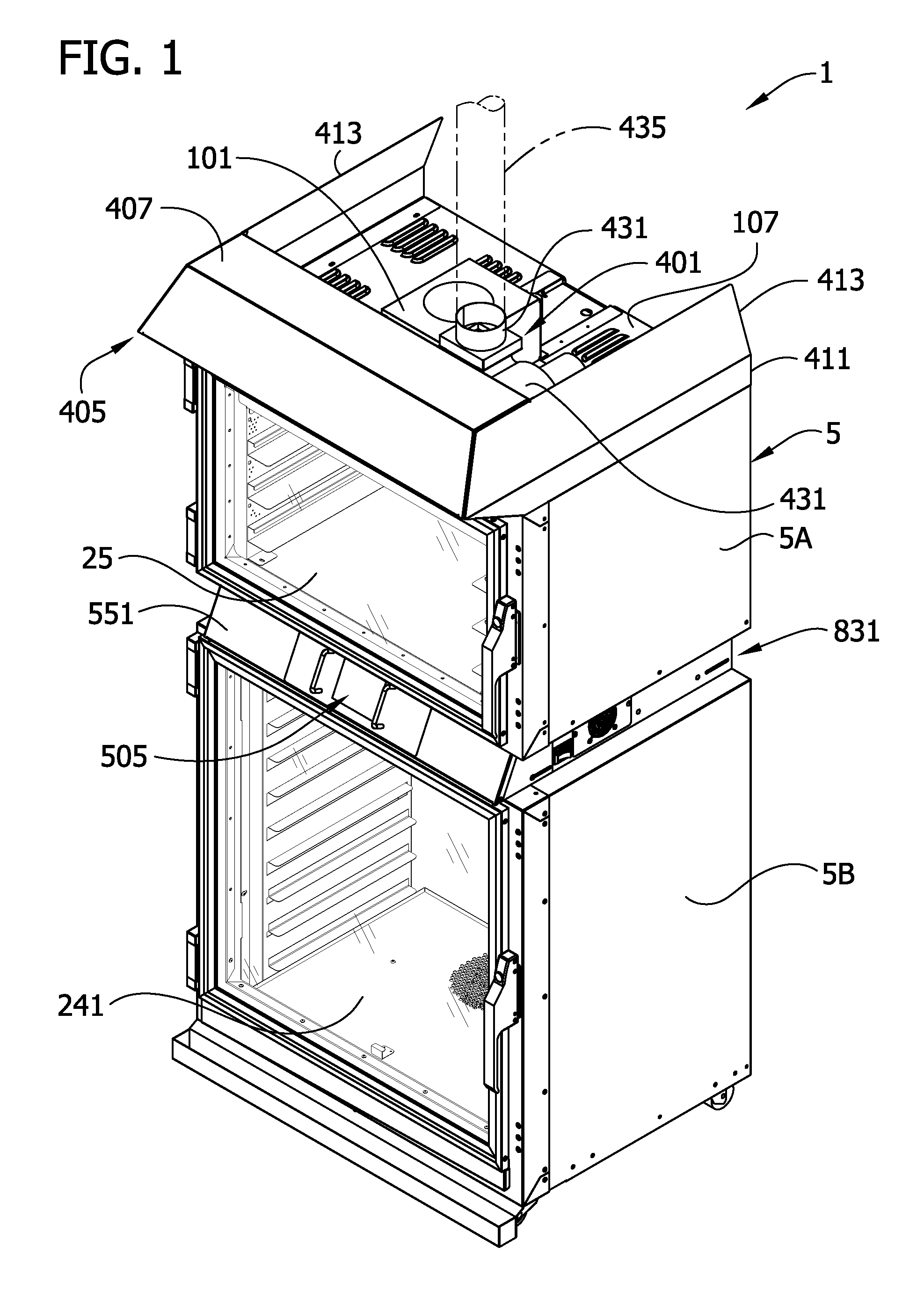
[0051]Referring to the drawings, FIG. 1 illustrates one embodiment of an oven of this invention, indicated generally by the reference number 1. The oven is adapted for cooking and baking products such as bread, among other things, and includes a cabinet, generally designated 5, having an upper section 5A and a lower section 5B. If the oven 1 is used in a bread making process, the dough is first proofed in the lower section 5B of the oven and then baked in the upper section 5A. (As will be understood by those skilled in the bread-making field, “proofing” is a continuation of the process of yeast fermentation which increases the volume or “rise” of the shaped dough, and an oven used to “proof” bread is often referred to as a “proofer” or “proofer oven.”)

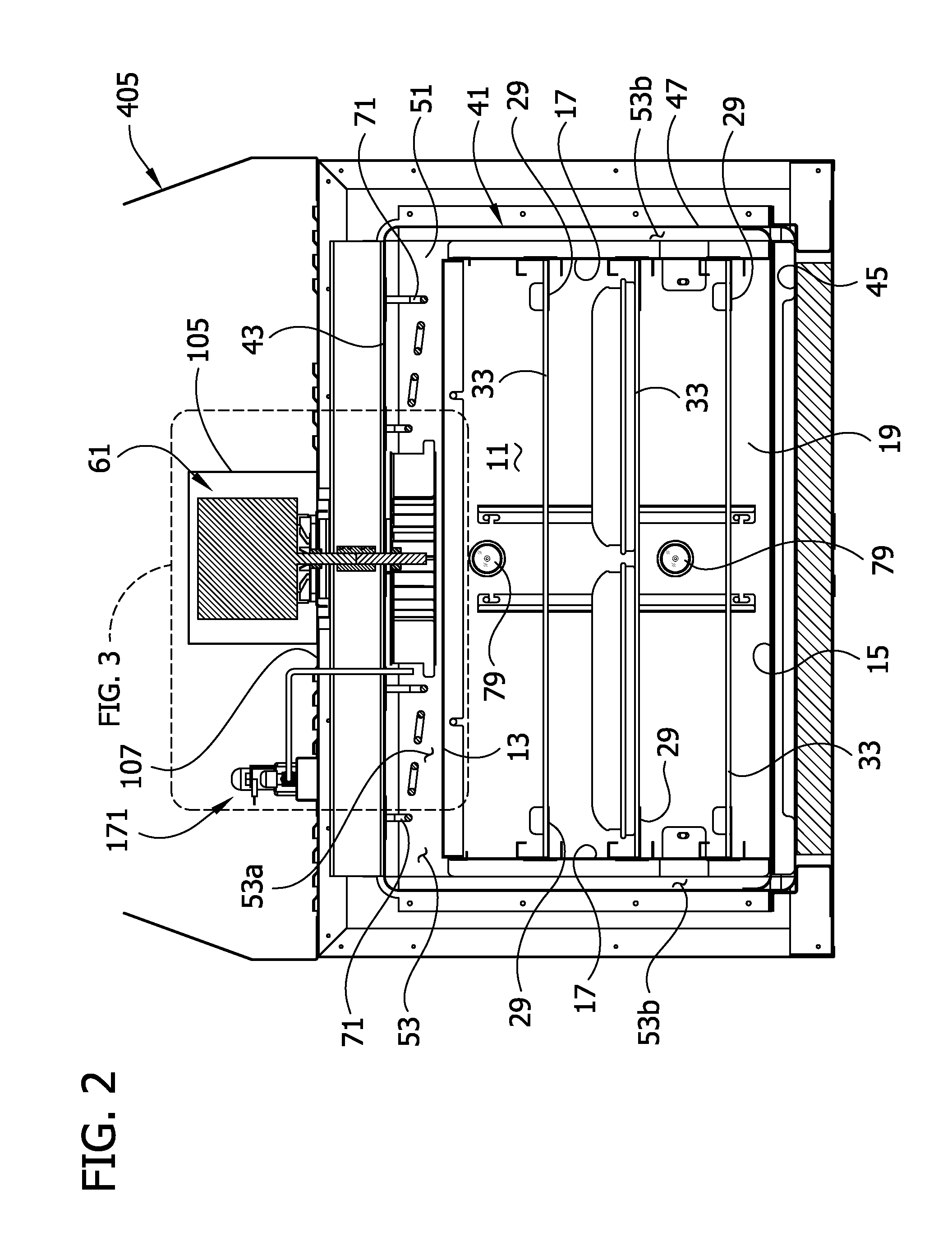
[0052]Referring to FIGS. 1-3, the upper section 5A of the oven 5 comprises a cooking (e.g., baking) chamber 11 defined by a top wall 13, a bottom wall 15, opposite side walls 17, and a back wall 21. The chamber 11 is accessible by open...


PUM


Abstract

A convection oven having a vapor collection system; water injection system; easily accessible electrical components; and a variable-speed, reversible blower is disclosed. The vapor collection system collects vapor from the cooking chamber during a cooking event, condenses the vapor, and drains the condensed vapor. The water injection system injects water for impact against a blower wheel for dispersion into the air circulating through the cooking chamber. The electrical components are housed within a housing that in a closed position conceals the components and in a closed position exposes the components for easy access. The rotational speed and direction of the variable-speed, reversible blower is controlled during a cooking event according to predetermined speed curves which may include one or more reversal events to achieve more uniform cooking of food. A main controller is programmable via an operator input (e.g., liquid crystal display touch screen) to control operating parameters of the oven.

Description

CROSS-REFERENCE TO RELATED CASES[0001]This application is a continuation application claiming priority from PCT Patent Application No. PCT / US2009 / 032251, filed Jan. 28, 2009 which claims priority to U.S. Patent Application No. 61 / 024,095 (provisional), filed Jan. 28, 2008, which is hereby incorporated by reference in its entirety.FIELD OF THE INVENTION[0002]The present invention generally relates to ovens and more particularly to a forced-air convection oven for baking bread products, among other things.BACKGROUND OF THE INVENTION[0003]Certain types of food products are especially difficult to cook quickly and uniformly. Bread is one such product. For proper cooking, the inside of the dough needs to be completely baked while the crust uniformly browns to the desired color. Conventional bread-baking ovens have various drawbacks.[0004]For example, conventional ovens do not provide convenient access to electrical components of the ovens for servicing or other purposes. Typically, a con...

Claims


Application Information

Patent Timeline
Patent Type & Authority Patents(United States)
IPC IPC(8): A21B1/00A21B1/26F27D19/00F24C15/00
CPCF24C7/082F24C15/327F24C7/006A21D8/06A21B1/26
Inventor GREENWOOD, JACKREESE, ROBERT J.
Owner DUKE MANUFACTURING COMPANY
Why Eureka
Try Eureka