
Micro fluid device having piping to control fluid temperature

a micro fluid and fluid temperature technology, applied in the field of micro fluid devices, can solve the problems of inability to rapidly stop reaction or inability to rapidly stop reaction or perform precipitation reaction for producing fine particles, and inability to rapidly stop reaction, etc., to achieve accurate change in fluid temperature, prevent fluid flow, and accurately detect the effect of temperature chang

Inactive Publication Date: 2013-02-26
FUJIFILM CORP
View PDF29 Cites 2 Cited by
  • Summary
  • Abstract
  • Description
  • Claims
  • Application Information

AI Technical Summary

Benefits of technology

The present invention aims to provide a micro fluid device that can accurately control the temperature of fluid flowing through a fine channel and prevent it from getting retained in the structure of the device. This is important in cases where multiple units are coupled together. The technical effect of the invention is the ability to accurately control fluid temperature and prevent it from getting trapped in the device's structure.

Problems solved by technology

The micro fluid devices in Japanese Patent Application Laid-Open Nos. 2006-61903 and 2006-159165 cover the periphery of the fine channel with heat insulating materials to enable reducing heat transfer between the fine channel and the outside, however, the micro fluid devices have a drawback in that they cannot rapidly stop reaction or perform precipitation reaction for producing fine particles because no device is provided to accurately change the temperature of the fluid.
Coupling portions are coupled with a plurality of tubes or connectors, causing a problem in that a dead space is liable to be formed at a connector portion and the temperature of fluid is liable to be scattered due to a subtle difference in length of the tubes.

Method used


Image

  • Micro fluid device having piping to control fluid temperature
  • Micro fluid device having piping to control fluid temperature
  • Micro fluid device having piping to control fluid temperature

Examples


embodiment

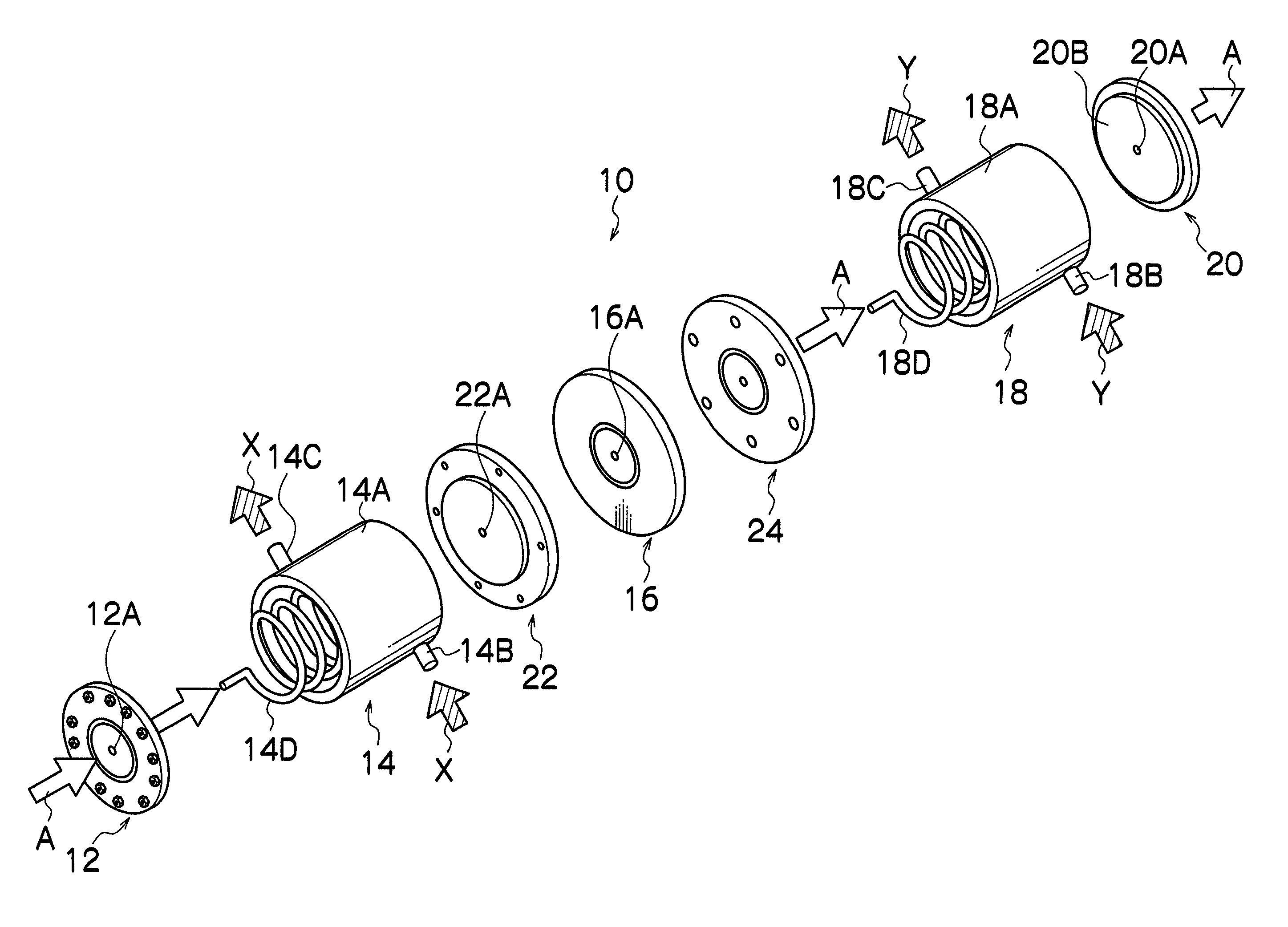
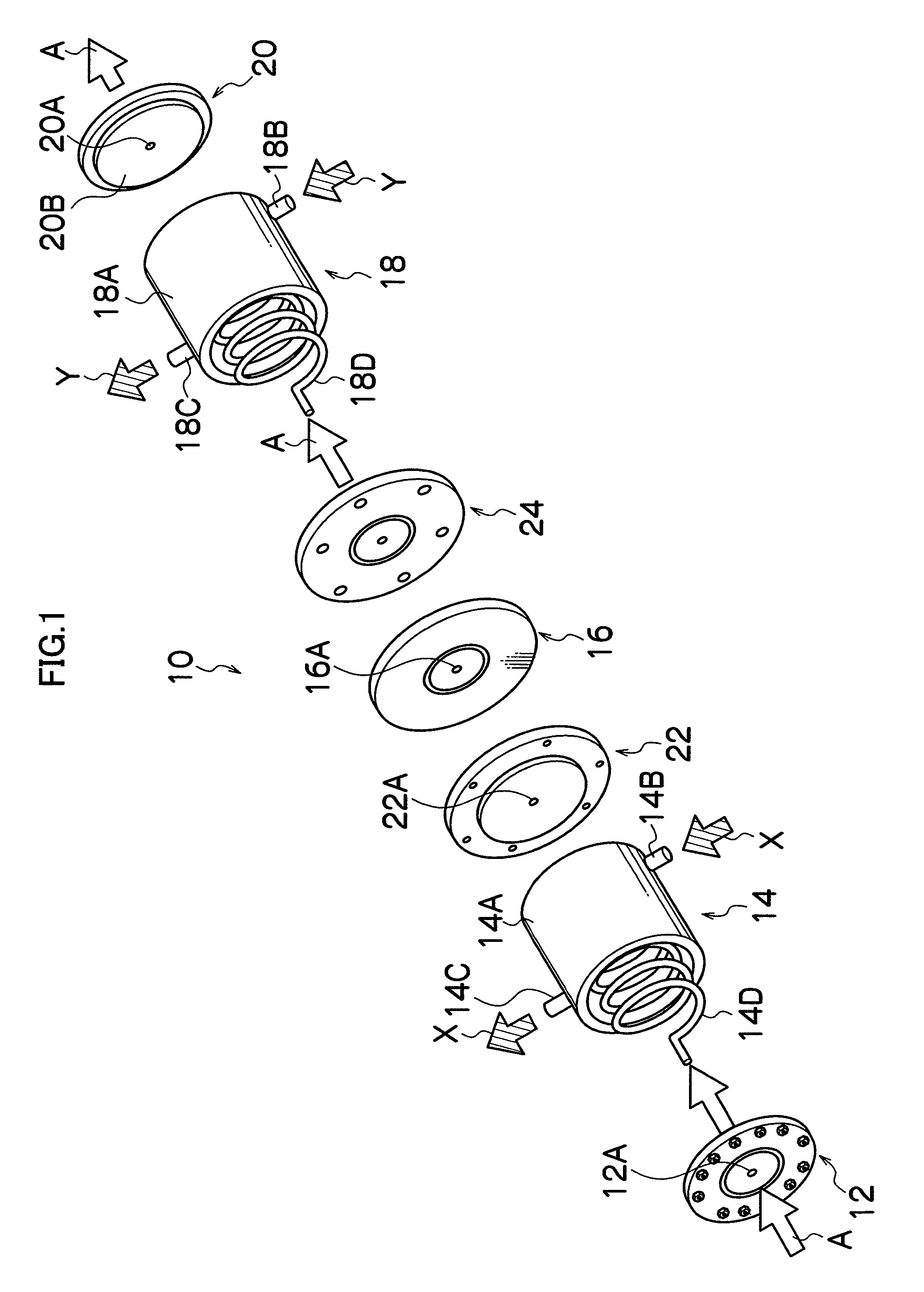
[0061]The present embodiment is such that the micro fluid device 10 of the present invention illustrated in FIG. 1 is applied to a process for producing fine particle dispersion liquid (emulsion dispersion material) using a phase-inversion temperature emulsification reaction. In the phase-inversion temperature emulsification reaction, the fluid A is accurately heated to a predetermined temperature and then quenched to precipitate solute, thereby obtaining fine particle dispersion liquid.

[0062]As fluid supplied to the micro fluid device 10, the liquid A was used in which water is mixed with cyclohexane at a ratio of water of 54.6% by mass to cyclohexane of 36.4% by mass and then mixed with polyoxyethylene (POE) of 9% by mass. It is known that the liquid A develops a phase-inversion temperature emulsification phenomenon and the balance of hydrophilicity and lipophilic of POE inverts at a phase-inversion temperature of 60° C. to 65° C., and the liquid A becomes a system in which cycloh...


PUM


Abstract

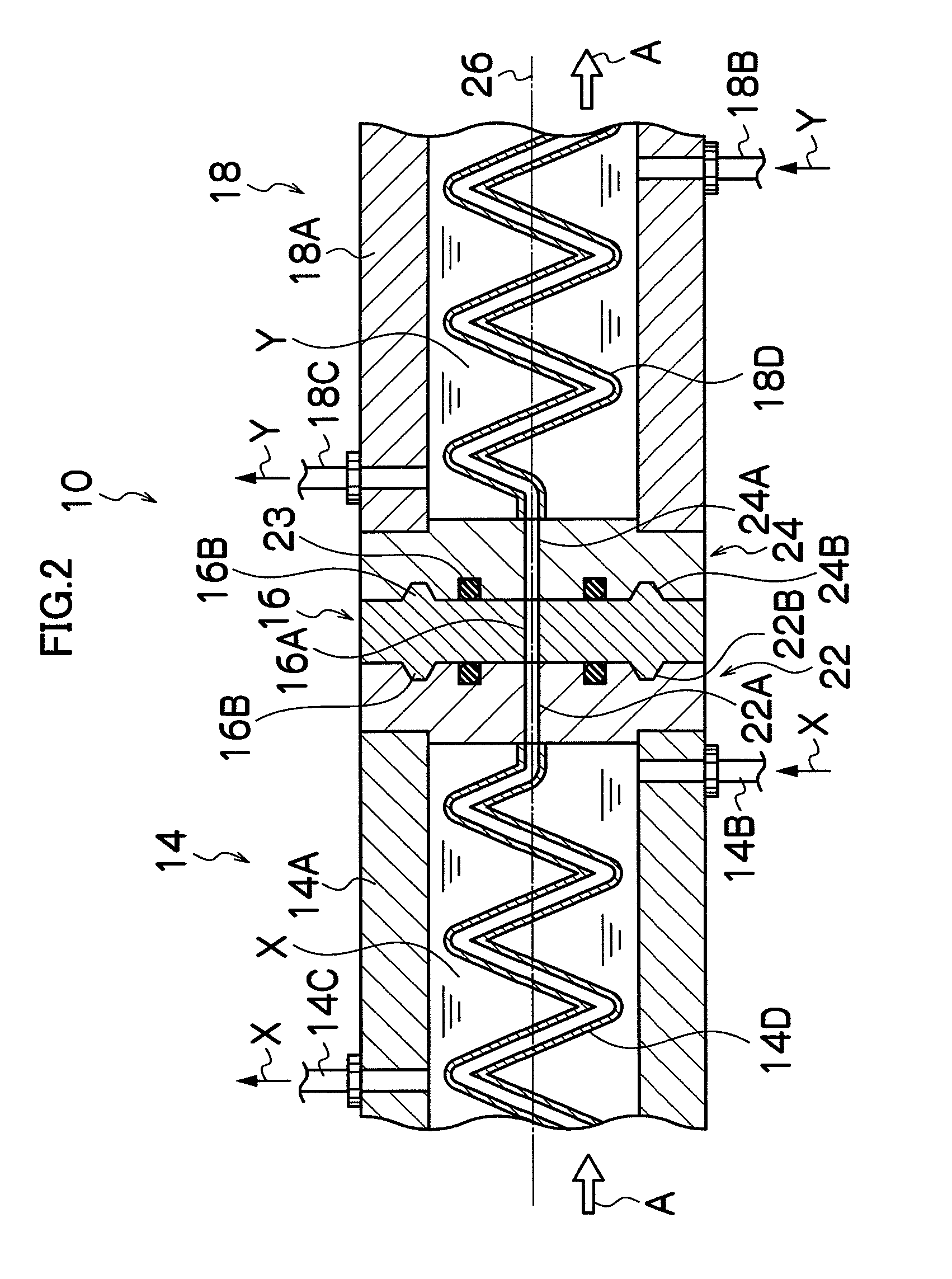
A micro fluid device includes a heating unit and a cooling unit, each with piping disposed within. The heating and cooling units are integrally coupled together, and fluid flows into the piping of respective units. A temperature control device includes a heat insulator which has a through hole equal in diameter to the piping disposed within the heating unit and cooling unit. The heat insulator is interposed between heating unit and the cooling unit. A positioning mechanism positions the heat insulator to bring the piping into communication with the through hole at the time of coupling the heating and cooling units.

Description

BACKGROUND OF THE INVENTION[0001]1. Field of the Invention[0002]The present invention relates to a micro fluid device, and in particular, to a micro fluid device with a function to accurately control change in temperature of fluid flowing through a fine channel.[0003]2. Description of the Related Art[0004]A micro fluid device with a fine channel has such a superior feature as to enable accurately controlling change in temperature of fluid flowing through a fine channel. And the micro fluid device is used as a device in a micro chemical process where various unit operations such as reaction, mixing, extraction and separation are performed. Unit operations by the micro fluid device require operations in which temperature of reactants is increased to a predetermined degree to accelerate reaction and then to quench to stop the reaction or solution into which solute high in temperature dissolves is quenched to accurately precipitate the solute. In particular, in the case where fine parti...

Claims


Application Information

Patent Timeline
Patent Type & Authority Patents(United States)
IPC IPC(8): B60H1/00F28F13/00F28F7/00F28D1/06
CPCB01J19/0093F28D7/024F28F9/26F28F27/00B01J2219/00788B01J2219/0081B01J2219/00873F28F2260/02
Inventor FUJIWARA, TAKAYUKIFUJISAWA, MAMORUMIYOSHI, YOSHIYUKI
Owner FUJIFILM CORP
Learn More