Endoscope testing device and method of using same

a technology of endoscope and testing device, which is applied in the field of endoscope testing device, can solve the problems of endoscope stress, bending or breaking of endoscope, chipping or dislocating glass lenses and deflection prisms,

Active Publication Date: 2013-02-26
INTEGRATED MEDICAL SYST INT INC
View PDF42 Cites 11 Cited by
  • Summary
  • Abstract
  • Description
  • Claims
  • Application Information

AI Technical Summary

Benefits of technology

[0008]According to another aspect of the invention, there is provided a method of making an endoscope testing device. The method includes coupling a cover to a base thereby forming an enclosure, coupling an optical test target to an interior surface of the cover, coupling an endoscope support stand to the enclosure, and supporting a plurality of endoscope testing devices within the base. Further, a white layer or sheet can be coupled to the interior surface of the cover. Preferably, the endoscope support stand is pivotably coupled to the interior surface of the cover using a bracket and a pair of magnets. In this way, the endoscope support stand can be oriented substantially upright in a testing position when the cover is open and substantially horizontal when the cover is closed.

Problems solved by technology

Because of the extreme physical dimensions of endoscopes, endoscopes are often stressed during cleaning, sterilization and usage.
These stresses can bend the endoscopes or break, chip or dislocate the glass lenses and deflection prisms.
Further, the illumination fibers can break, and debris can accumulate on the ends of the fiber illumination bundle or on the windows enclosing the optical system.
Accordingly, endoscopes can be damaged or their performance degraded to an extent where the safe usage of the instruments is no longer warranted.
If the damage is not detected prior to the planned surgery the medical procedure can be delayed, cancelled or the outcome of the procedure can be compromised.
These testing devices are easy to use but do not give a clear determination if the equipment is ready for use or not.
These devices are less complicated to operate, but they are expensive and delicate.

Method used


Image

  • Endoscope testing device and method of using same
  • Endoscope testing device and method of using same
  • Endoscope testing device and method of using same

Examples


Embodiment Construction

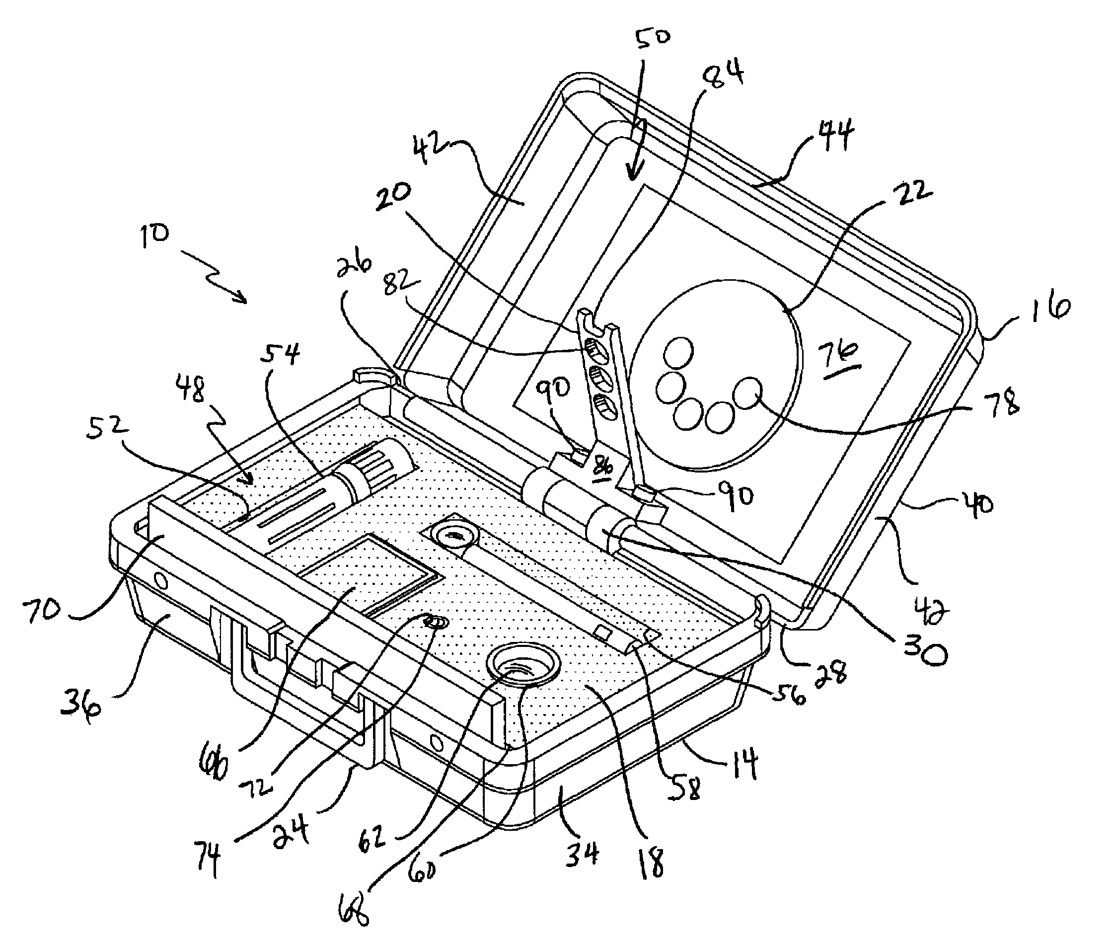
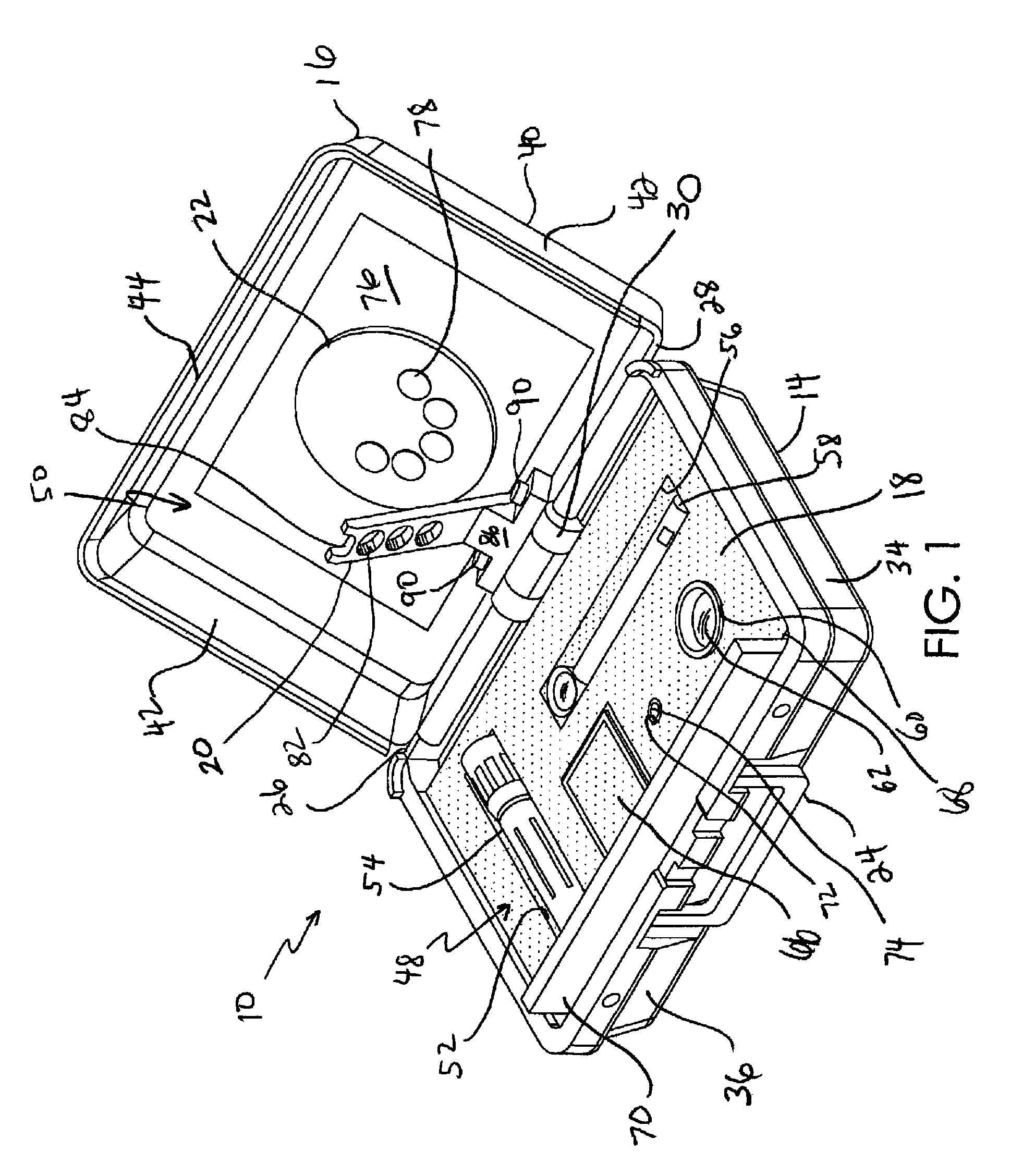
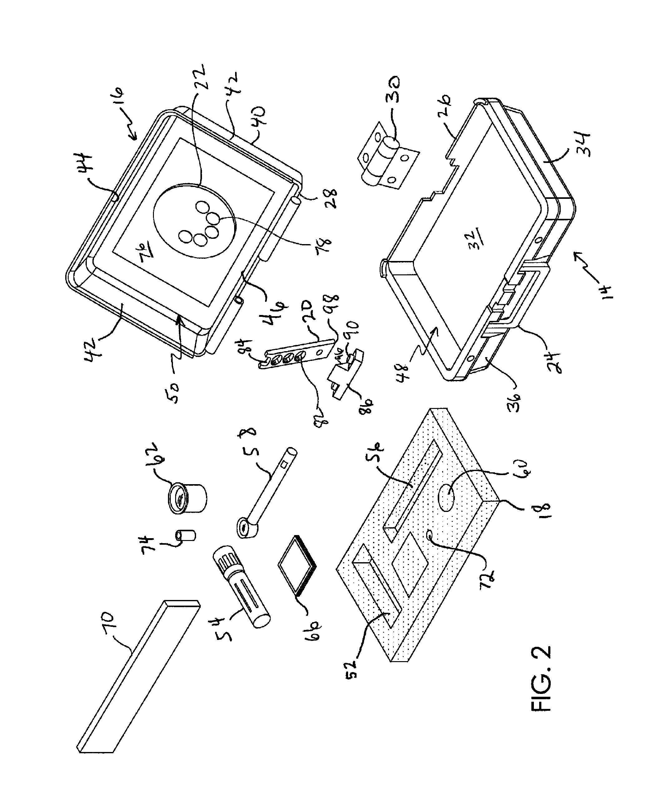
[0015]FIGS. 1 through 6 display a portable endoscope testing device 10 in accordance with a preferred embodiment of the present invention. Referring to FIGS. 1 and 2, testing device 10 generally includes a case or enclosure 12 composed of a base 14 and a cover 16. Base 16 is provided for securely accommodating a variety of endoscope testing devices within a foam bed 18 held within the base. Cover 16 is provided for supporting a monopod or endoscope support stand 20 and an optical test target 22 that is aligned with stand 20. As described in more detail below, enclosure 12 is maintained in a closed position when device 10 is in storage, not in use or during transportation of the device. Alternatively, when testing device 10 is to be used to test an endoscope, enclosure 12 is oriented into an open position thus exposing the variety of endoscope testing devices and maneuvering support stand 20 into a testing position.

[0016]More particularly, enclosure 12 is provided in the form a small...


PUM


Abstract

The invention relates to test equipment for rigid endoscopes, but also for flexible endoscopes and video endoscopes. The equipment includes an enclosure having a cover hingedly coupled to a base, an optical test target coupled to the cover, an endoscope support stand pivotably coupled to the enclosure and a bed contained within the base including a plurality of indentations shaped for receiving individual pieces of endoscope testing equipment. The testing equipment can include magnification loupes, light post adapters, battery powered light sources, cleansing tissues and a ruler. A support bracket is coupled between the cover and the endoscope support stand wherein the endoscope support stand is pivotably coupled to the support bracket.

Description

FIELD OF THE INVENTION[0001]The present invention is directed to device for testing optical equipment, and more particularly, to a portable testing kit and method of using same for testing the optical system and the illumination system of an endoscope.BACKGROUND OF THE INVENTION[0002]Technical and medical endoscopes are delicate optical instruments that are introduced into technical and human cavities to inspect the interiors thereof. Such endoscopes can be rigid endoscopes containing a lens system, flexible endoscopes containing a flexible image guiding bundle or video endoscopes. Typically, endoscopes contain an outer tube and an inner tube. The space between the outer tube and the inner tube is filled with illumination fibers which guide externally created light inside of the cavities. Within the inner tube of rigid endoscopes there is provided an optical system which relays an image of the cavity from the distal tip of the endoscope back to the proximal end of the endoscope. Thi...

Claims


Application Information

Patent Timeline
Patent Type & Authority Patents(United States)
IPC IPC(8): A61B1/00
CPCA61B1/00057
Inventor BODOR, ZOLTAN A.GOODALE, MATTHEW T.WILLIAMS, OSCAR JEROMETODOR, MARIUSYE, SHUSHENGZOBEL, JURGEN
Owner INTEGRATED MEDICAL SYST INT INC
Why Eureka
Try Eureka