Separating and stripping apparatus for external FCC risers

a technology of separating and stripping apparatus and riser, which is applied in the direction of lighting and heating apparatus, furnace types, furnaces, etc., can solve the problems of inability to achieve, inability to achieve, and inevitable loss of stripping efficiency in the stripping zone, so as to reduce the efficiency of catalyst collection

Active Publication Date: 2013-02-26
STONE & WEBSTER PROCESS TECH
View PDF18 Cites 5 Cited by
  • Summary
  • Abstract
  • Description
  • Claims
  • Application Information

AI Technical Summary

Benefits of technology

[0015]The inlet opening (48) comprises at least one gas flow direction change means (48a) defined in part by one outer wall of the stripping chamber (49) located above the inlet opening (48). The gas flow direction change means (48a) receives separated cracked gases traveling vertically upward after separation from spent catalyst particles in the separating chamber (50). More particularly, the mixture of cracked gases and spent catalyst particulates travels through the riser cross-over conduit (46) and enters the separating chamber (50) where it impacts partitioning baffle (47) located opposite the entrance of the riser cross-over conduit (46) which separates the horizontally traveling mixture of cracked gases and spent catalyst into two streams traveling around the circumference of the separating chamber (50). A baffle (47a) positioned opposite the partition baffle (47) and above the flow direction means (48a) in the separating chamber (50), prevents the two catalyst laden vapor mixtures from colliding and causing a catalyst cloud, which would reduce catalyst collection efficiency. The catalyst then travel downwardly through the separating chamber (50) and enters diplegs (37). The separated vapors conversely travel upwardly through the opening (48) and enter the stripping chamber (49).

Problems solved by technology

And while it is relatively simple to carry out rapid separation or effective stripping, it is difficult to carry out rapid separation and effective stripping substantially simultaneously.
A further disadvantage of that separation system is that it introduces hydrocarbons entrained or adsorbed onto the catalyst in localized fashion into the fluidized stripping bed.
Because the fluidized bed is a poor radial mixer but a very good axial mixer, there is an inevitable loss of efficiency in the stripping zone.
Nevertheless, this would only be effective if the catalyst flowed slowly in the cyclone outlet in order not to entrain gases, which is not possible to achieve if proper operation of the primary cyclones is to be retained.

Method used


Image

  • Separating and stripping apparatus for external FCC risers
  • Separating and stripping apparatus for external FCC risers
  • Separating and stripping apparatus for external FCC risers

Examples


Embodiment Construction

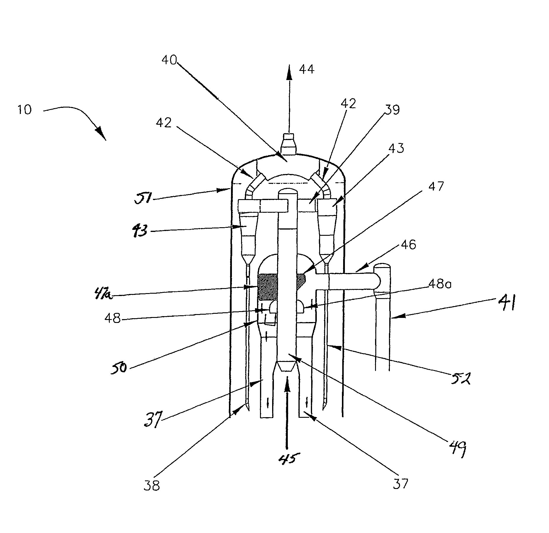
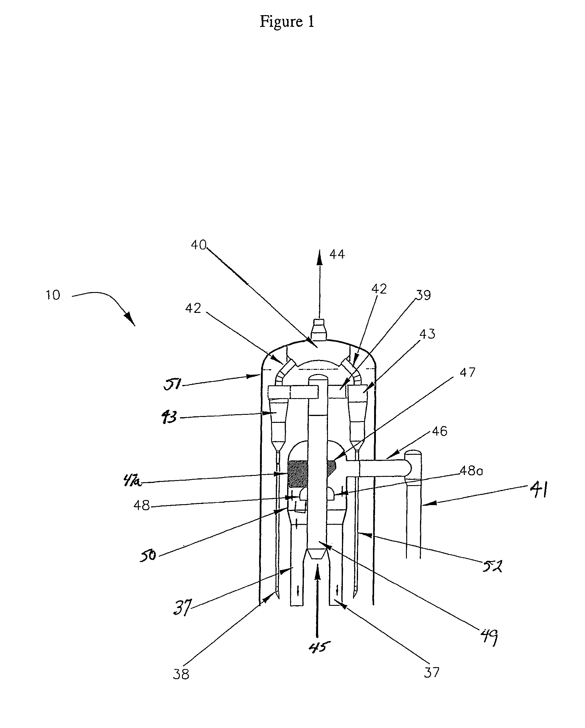
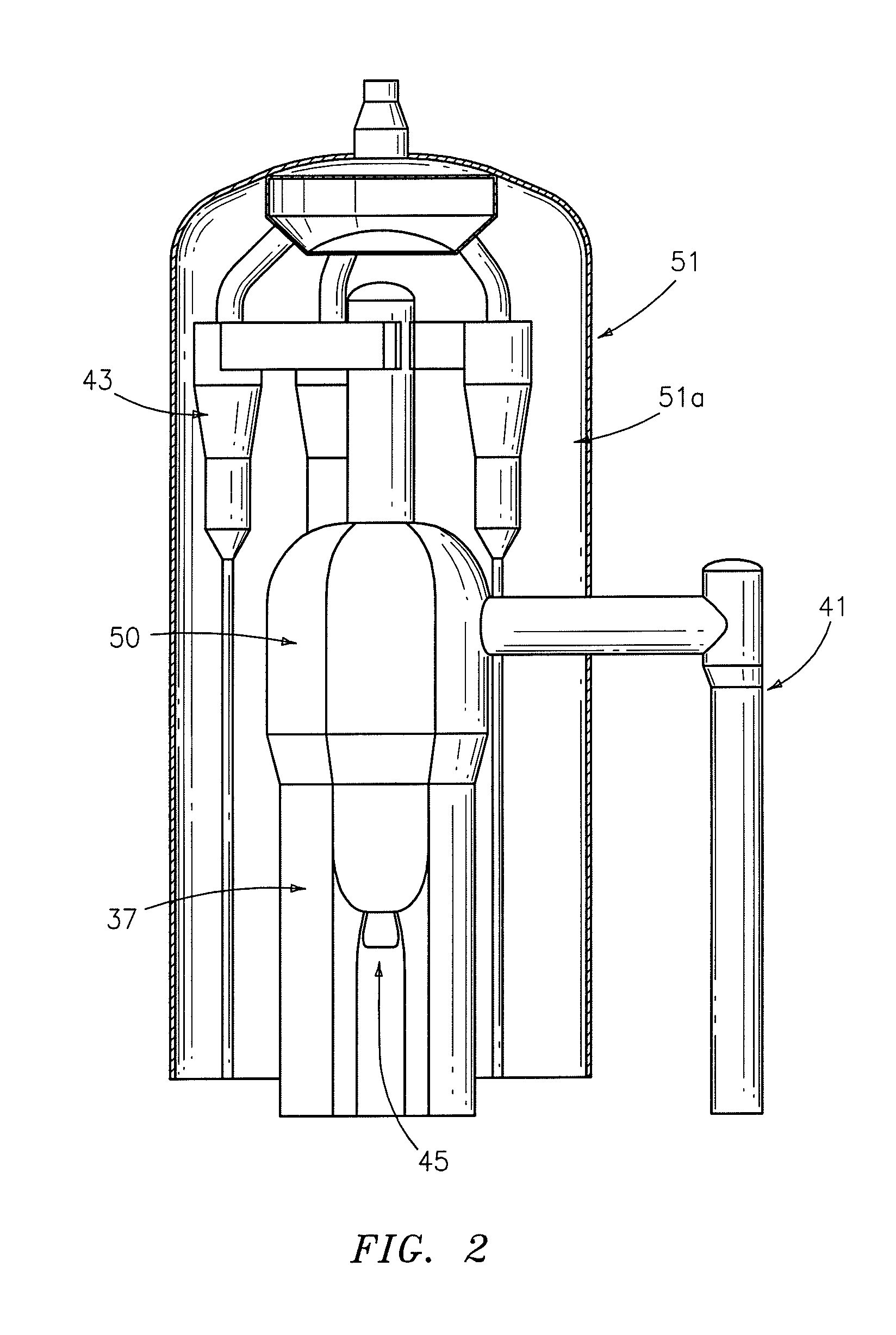
[0023]The present invention broadly is directed to an apparatus (10) for separating hydrocarbons and / or other gases from solid particles, such as a particulate catalyst and / or other particles (including inert particulates), which are typically finely divided and porous, in a mixture containing the gases and solid particles, for example, an apparatus for the fluidized catalytic cracking (FCC) of hydrocarbons. This mixture may be an effluent that exits an outlet of a different reactor, for example, one that brings an essentially gaseous phase into contact with a solid phase. The apparatus generally includes a compartmentalized arrangement of one or more reactors, chambers, conduits, inlets, outlets, baffles and diplegs, and an external riser reactor pipe, with communication between many of these components, and according to one preferred embodiment of the invention, can beneficially produce a hydrocarbon gas that contains less than about 0.05 percent of solids by weight, and in anothe...


PUM

PropertyMeasurementUnit
surface velocityaaaaaaaaaa
diameteraaaaaaaaaa
diameteraaaaaaaaaa

Abstract

The present invention provides a compact riser separation system for Fluid Catalytic Cracking reactors possessing an external riser system wherein the riser enters the reactor from outside the reactor vessel.

Description

FIELD OF THE INVENTION[0001]The invention relates to a separating and stripping apparatus and its use in a process for catalytic cracking of hydrocarbons. More particularly, the present invention relates to rapid separation and effective stripping of catalytically cracked hydrocarbon streams in a disengaging apparatus having a compact riser separation system, wherein an external riser that enters the disengaging apparatus from the outside.BACKGROUND OF THE INVENTION[0002]Fluid Catalytic Cracking (FCC) is a commonly-used process in oil refineries that produces high yields of gasoline and liquefied petroleum gas, which are in a high demand in the United States, and throughout the world. Despite the long existence of the fluidized catalytic cracking process, techniques are continually sought for improving product recovery both in terms of product quantity and composition, i.e., yield and selectivity.[0003]In general, commercial fluid catalytic cracking processes are carried out in FCC ...

Claims


Application Information

Patent Timeline
Patent Type & Authority Patents(United States)
IPC IPC(8): B01J8/24C10G47/30
CPCC10G11/182C10G2300/4093F27B15/08F27B15/09
Inventor GBORDZOE, EUSEBIUS ANKUSANTNER, CHRIS ROBERT
Owner STONE & WEBSTER PROCESS TECH
Why Eureka
Try Eureka