High-speed centrifugal spinning device for preparing nanofibers

A technology of nanofiber and high-speed centrifugation, which is applied in fiber processing, textile and papermaking, and melting of filament raw materials. It can solve the problems of low production efficiency, conductivity constraints, and high cost, and achieve high production efficiency without conductivity. The effect of constraints

Active Publication Date: 2018-11-23
德州纺兴纤维有限公司
View PDF6 Cites 2 Cited by
  • Summary
  • Abstract
  • Description
  • Claims
  • Application Information

AI Technical Summary

Problems solved by technology

However, electrospinning also has the following inherent defects: (1) high-voltage electric field needs to be applied during the preparation process, the cost is high, and safety issues require additional attention; (2) the production efficiency is low; (3) the solution requires a certain proportion of solvent to make the solution have a certain conductivity, which can lead to contamination
Although this design can improve the order degree of fibers, realize the mass production of oriented nanofibers to a certain extent, and increase the output, it still needs to apply a high-voltage electric field, which is still limited by the conductivity, and the production efficiency is low.

Method used


Image

  • High-speed centrifugal spinning device for preparing nanofibers
  • High-speed centrifugal spinning device for preparing nanofibers
  • High-speed centrifugal spinning device for preparing nanofibers

Examples


Embodiment 1

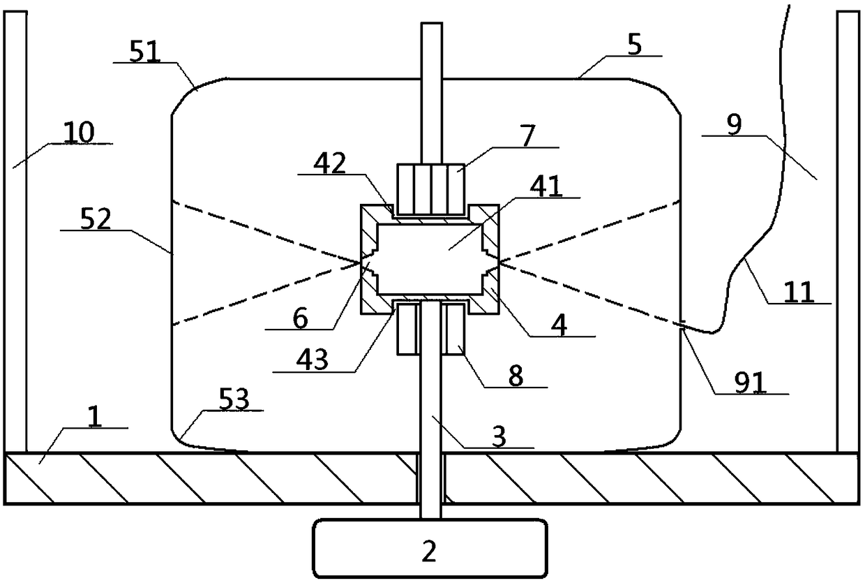
[0042] see Figure 1 to Figure 3 , a high-speed centrifugal spinning device for preparing nanofibers, comprising a filling rotor 4, a rotating shaft 3 and a collecting device 5, the filling rotor 4 communicates with a nozzle 6, the inside of the filling rotor 4 is filled with a polymer, and the filling rotor The bottom of 4 is connected with the rotating shaft 3, and a collecting device 5 is arranged around the rotor 4;

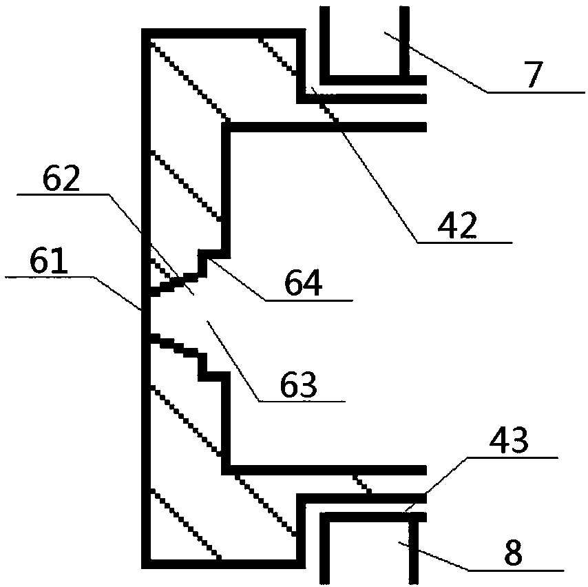
[0043] The inside of the material-filling rotor 4 is provided with a material-filling cavity 41, and a polymer is arranged in the material-filling cavity 41, and a nozzle 6 communicating with the material-filling cavity 41 is provided on the side wall of the material-filling rotor 4, and the material-filling rotor 4 An upper heater 7 and a lower heater 8 are arranged on the upper and lower sides respectively, the bottom of the rotor 4 is connected to the top of the rotating shaft 3, and the bottom of the rotating shaft 3 passes through the base 1 and is conne...

Embodiment 2

[0046] Basic content is the same as embodiment 1, the difference is:

[0047] The top and the bottom of the rotor 4 are respectively provided with a top groove 42 and a bottom groove 43, the top groove 42 is provided with the bottom of the upper heater 7, and the top of the upper heater 7 is extended to the top of the material. Directly above the rotor 4 , the bottom groove 43 is provided with the top of the lower heater 8 , and the bottom of the lower heater 8 extends down to directly below the rotor 4 . The lower heater 8 is sleeved on the outer wall of the rotating shaft 3 , and the junction of the rotating shaft 3 and the material-filling rotor 4 is set higher than the top of the lower heater 8 .

Embodiment 3

[0049] Basic content is the same as embodiment 1, the difference is:

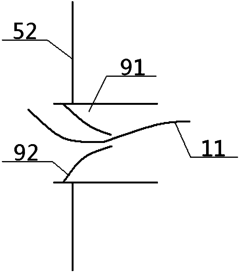
[0050] The collection device 5 is a cylindrical structure with openings at both ends. The side enclosure of the collection device 5 includes an upper inner arc edge 51, a middle vertical edge 52 and a lower inner arc edge 53. The upper inner arc edge 51 passes through the middle vertical edge 52, The lower inner arc edge 53 is then connected to the top surface of the base 1, and the upper inner arc edge 51 and the lower inner arc edge 53 are both inner turning structures.


PUM


Abstract

The invention relates to a high-speed centrifugal spinning device for preparing nanofibers. The device comprises a material containing rotor, a rotation shaft, an upper heater, a lower heater and a collection device. A polymer is arranged in a material containing cavity in the material containing rotor, a spray nozzle communicated with the material containing cavity is formed in the side wall of the material containing rotor, and the upper heater and the lower heater are arranged on the upper and lower portions of the material containing rotor respectively; the bottom of the material containing rotor is connected with the top of the rotation shaft, a collection device is arranged on the exteriors of the material containing rotor and the heater, a taking cavity is sandwiched between the collection device and an external insulation wall, and the nozzle inner cavity of the spray nozzle is of a circular truncated cone structure. According to the device, a high-voltage electric field does not need to be applied, the device is not restrained by conductivity, the production efficiency is high, the collection effect is good, the yarn taking efficiency is high, and the application range iswide.

Description

technical field [0001] The invention relates to a nanofiber production equipment, in particular to a high-speed centrifugal spinning device for preparing nanofibers, which is particularly suitable for avoiding the defects of high-voltage electric field and conductivity constraints, and improving production efficiency. Background technique [0002] Nanofibers refer to ultrafine fibers with a diameter of tens to hundreds of nanometers, which have unique advantages that other fibers cannot possess, such as very large specific surface area, ultrafine porosity, and good mechanical properties. In recent years, nanofibers have been widely used in textile materials, tissue engineering scaffolds, drug delivery, filter media, artificial blood vessels, biochips, nanosensors, optics, composite materials and other fields. [0003] The preparation of nanofibers has attracted the attention of experts and scholars at home and abroad. So far, there are many methods for preparing nanofibers,...

Claims


Application Information

Patent Timeline
Patent Type & Authority Applications(China)
IPC IPC(8): D01D5/18D01D1/04
CPCD01D1/04D01D5/18
Inventor 张智明段耀帅徐巧祖耀孙俊刘芳梅顺齐卢宾宾
Owner 德州纺兴纤维有限公司
Why Eureka
Try Eureka