Dedicated system for msk joint imaging

a technology of msk and joint, applied in the field of medical imaging, can solve the problems of insufficient system size, inability to achieve high-quality images, so as to facilitate joint imaging, reduce imaging volume, and improve patient comfort and openness

Inactive Publication Date: 2013-02-26
GENERAL ELECTRIC CO
View PDF25 Cites 0 Cited by
  • Summary
  • Abstract
  • Description
  • Claims
  • Application Information

AI Technical Summary

Benefits of technology

[0011]To achieve these and other advantages and in accordance with the purpose of the invention, as embodied herein, a new and useful system is presented that facilitates imaging of the joints of the upper and lower extremities including, for example, the hip and shoulder as well as sections of the spine. One embodiment of the invention includes a short bore cylindrical magnet with an imaging volume smaller than that of a comparable whole body system, an articulated table that allows placement of the joint to be imaged in the center of the magnet homogeneous volume while maintaining a high degree of patient comfort and openness.
[0012]In accordance with a further aspect of the invention, the gradient and RF coils may be positioned above and below the patient instead of 360 degrees surrounding the patient, as in prior art systems. This aspect may allow for a smaller magnet to be used with the same or improved left / right patient aperture. A smaller RF and gradient coil is made feasible because of the reduced imaging volume. The smaller RF coil requires less power for the same performance and reduce RF power deposition (SAR or Specific Absorption Rate) that can cause heating and less dB / dt (time rate of field) that can cause peripheral nerve stimulation.

Problems solved by technology

However, this can only help to a limited extent.
However, such systems are necessarily large.
These materials are expensive.
All of these factors increase the system costs.

Method used


Image

  • Dedicated system for msk joint imaging
  • Dedicated system for msk joint imaging
  • Dedicated system for msk joint imaging

Examples


Embodiment Construction

[0023]Reference will now be made in detail to the present preferred embodiments of the invention, examples of which are illustrated in the accompanying drawings. The method and corresponding steps of the invention will be described in conjunction with the detailed description of the system.

[0024]The devices and methods presented herein may be used for generating medical images. Particularly, the present invention is directed to a method and system for generating magnetic resonance (“MR”) images of a patient.

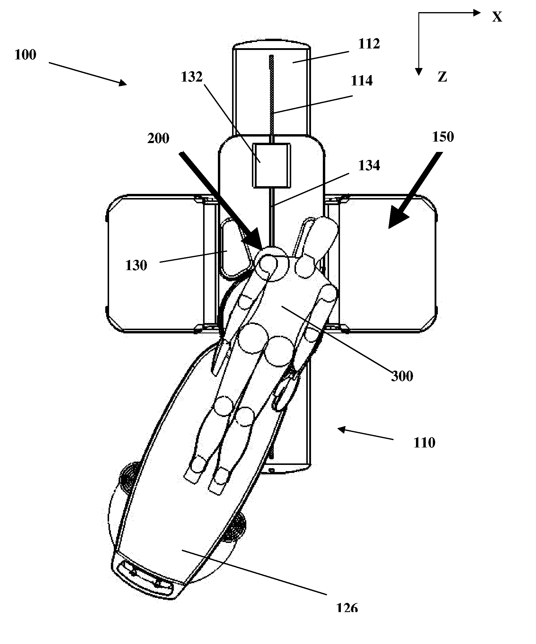
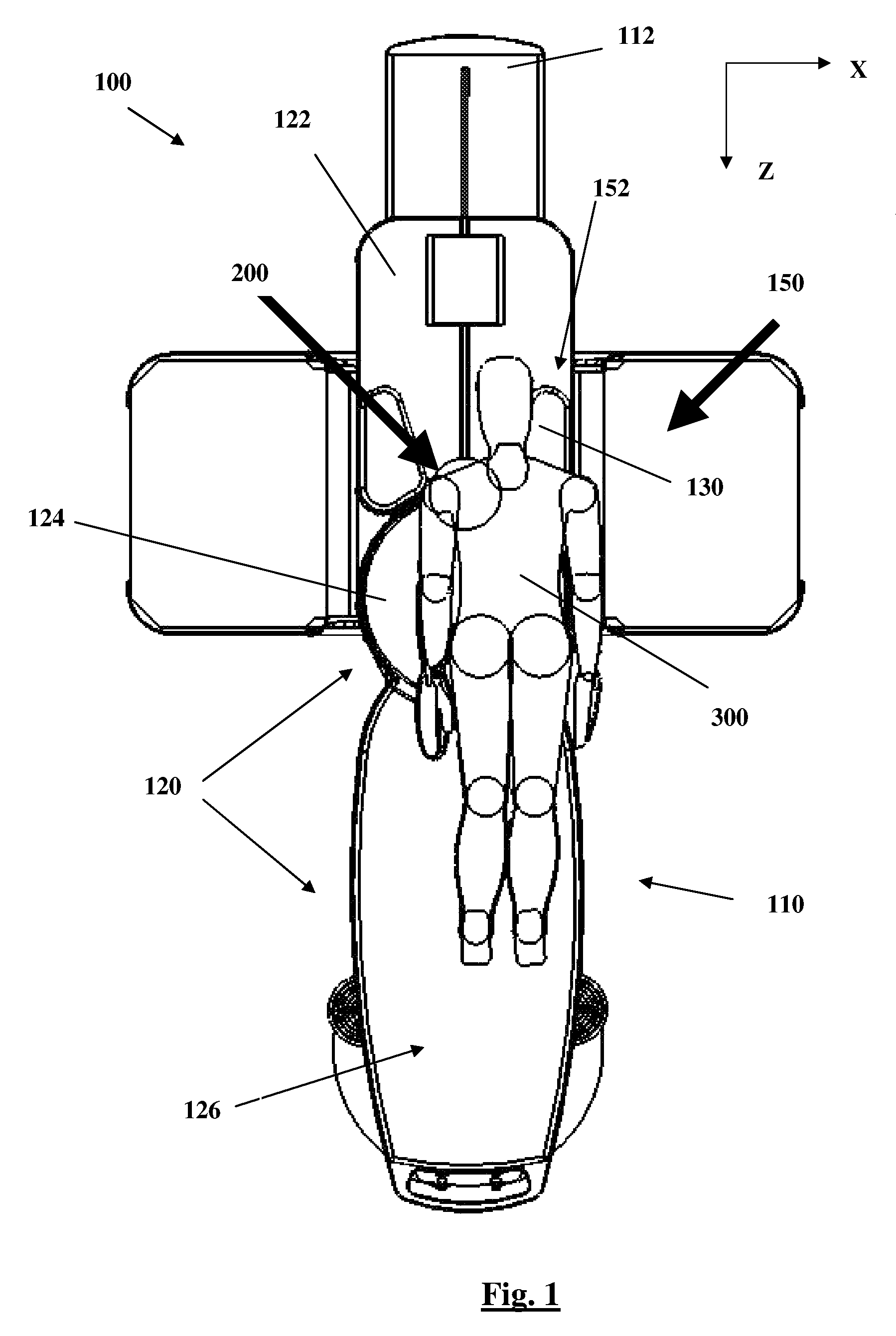
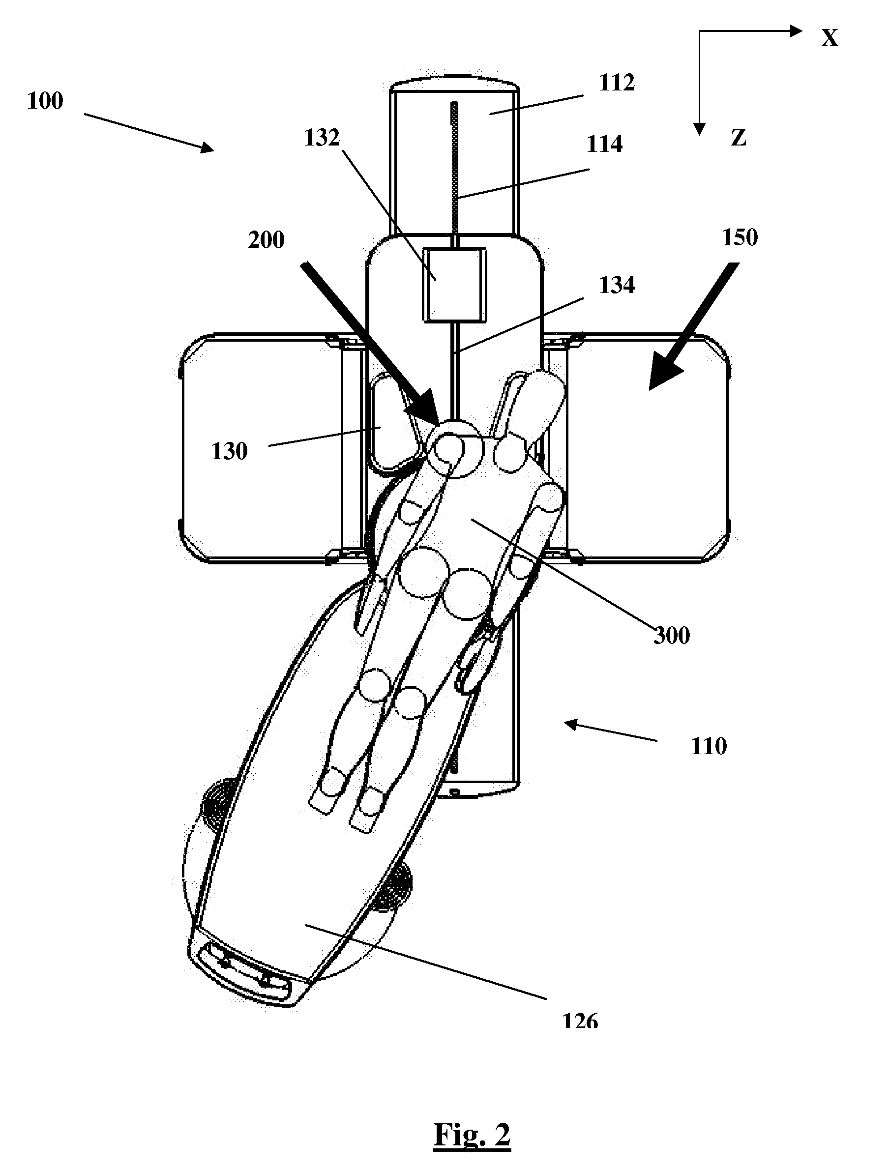
[0025]Embodiments of the invention depicted herein include a combination of magnet and articulated patient table that allow the hip, shoulder, foot, ankle, knee, hand, wrist and elbow joints to be positioned and imaged in a smaller cylindrical MRI magnet. Particular embodiments described herein allow all of the joints of interest of the human body to be centered in the magnet, yet permit use of a magnet with an associated homogenous volume that is substantially smaller than typic...


PUM


Abstract

A system and method are presented that facilitate imaging of the joints of the upper and lower extremities including, for example, the hip and shoulder as well as sections of the spine, among others. One embodiment of the invention includes a short bore cylindrical magnet with an imaging volume smaller than that of a comparable whole body system, an articulated table that allows placement of the joint to be imaged in the center of the magnet homogeneous volume while maintaining a high degree of patient comfort and openness. The gradient and RF coils may be positioned above and below the patient instead of 360 degrees surrounding the patient. A smaller RF and gradient coil is made feasible because of the reduced imaging volume.

Description

CROSS-REFERENCE TO RELATED APPLICATIONS[0001]This application is a continuation of and claims priority to International Patent Application No. PCT / US2008 / 006028, filed May 12, 2008, which in turn claims priority to U.S. Provisional Patent Application Ser. No. 60 / 928,622, filed May 10, 2007. Each of the aforementioned patent applications is incorporated by reference herein in its entirety.BACKGROUND OF THE INVENTION[0002]1. Field of the Invention[0003]The present invention relates to a method and system for generating medical images. Particularly, the present invention is directed to a method and system for generating magnetic resonance (“MR”) images of a patient.[0004]2. Description of Related Art[0005]A variety of systems and related methods are known in the art for generating magnetic resonance images of a patient. Currently, whole body MRI systems utilize, among other things, cylindrical superconducting magnets to facilitate imaging of the entire human body using linear moving pa...

Claims


Application Information

Patent Timeline
Patent Type & Authority Patents(United States)
IPC IPC(8): G01V3/00
CPCA61B5/055A61B5/4528G01R33/30G01R33/307A61B5/0555G01R33/3806
Inventor MCNULTY, CHRISTOPHERROEMER, PETER B.STEVENS, ROBERTCHENG, YUAN
Owner GENERAL ELECTRIC CO
Why Eureka
Try Eureka