System and method of identifying tagged articles

a technology of identifying system and identifying method, applied in the field of automatic collection of data, can solve the problems of inability to transmit data to the tag, high production cost of tags, and high cost of tags, and achieve the effect of reducing production costs, increasing production costs, and increasing production costs

Active Publication Date: 2013-02-26
MEPS REAL TIME
View PDF40 Cites 57 Cited by
  • Summary
  • Abstract
  • Description
  • Claims
  • Application Information

AI Technical Summary

Problems solved by technology

Data transmission to the tag is not possible.
These tags are very low cost and are produced in enormous quantities.
Programming each one of the tags with information contained in the article to which they are attached involves further expense.
Another choice is an active RFID tag; however, such tags require an accompanying battery to provide power to activate the tag, thus increasing the expense of the tag and making them undesirable for use in a large number of applications.
Additionally, in the U.S. and in other countries, the frequency range within which such tags are permitted to operate is limited.
At this frequency range, the electromagnetic energy is less affected by liquids and other dielectric materials, but suffers from the limitation of a short interrogating distance.
Additionally, metal surfaces of the enclosures present a serious obstacle for the RF signals that need to be exchanged between RFID readers and RFID tags, making RFID tags located behind those metal surfaces difficult or impossible to detect.
In addition to the above, the detection range of the RFID systems is typically limited by signal strength to short ranges, frequently less than about thirty centimeters for 13.56 MHz systems.
However, such an antenna may be unwieldy and may increase the range of the radiated power beyond allowable limits.
Furthermore, these reader antennae are often located in stores or other locations where space is at a premium and it is expensive and inconvenient to use such large reader antennae.
In another possible solution, multiple small antennae may be used but such a configuration may be awkward to set up when space is at a premium and when wiring is preferred or required to be hidden.
Cabinets such as these are typically made of metal, which can make the use of an external RFID system for identification of the stored articles difficult.
In some cases, such cabinets are locked due to the presence of narcotics or other medical articles or apparatus within them that are subject to a high theft rate.
Thus, manual identification of the cabinet contents is difficult due to the need to control access.
Providing an internal RFID system in such a cabinet can pose challenges.
In general, dead zones are areas in which the level of coupling between an RFID reader antenna and an RFID tag is not adequate for the system to perform a successful read of the tag.
Thus, articles placed in dead zones may not be detected thereby resulting in inaccurate tracking of tagged articles.
Often in the medical field, there is a need to read a large number of tags attached to articles in such an enclosure, and as mentioned above, such enclosures have limited access due to security reasons.
Generating such a robust EM energy field is not an easy task.
However, in the RFID field the usable frequencies of operation are strictly controlled and are limited.
Where the enclosure impedance changes due to the introduction or removal of articles to or from the enclosure, a static impedance matching circuit may not provide optimum energy transfer into the enclosure.
If the energy transfer and resulting RF field intensity within the enclosure were to fall below a threshold level, some or many of the tags on articles within the enclosure would not be activated to identify themselves, leaving an ineffective inventory system.
The use of high-power readers to locate and extract data from RFID tags is generally undesirable in health care facilities, although it may be acceptable in warehouses that are sparsely populated with workers, or in aircraft cargo holds.
Radiating a broad beam of EM energy at a large area, where that EM energy may stray into adjacent, more sensitive areas, is undesirable.
Additionally, this is a manual system that will require the services of one or more individuals, which can also be undesirable in facilities where staff is limited

Method used


Image

  • System and method of identifying tagged articles
  • System and method of identifying tagged articles
  • System and method of identifying tagged articles

Examples


Embodiment Construction

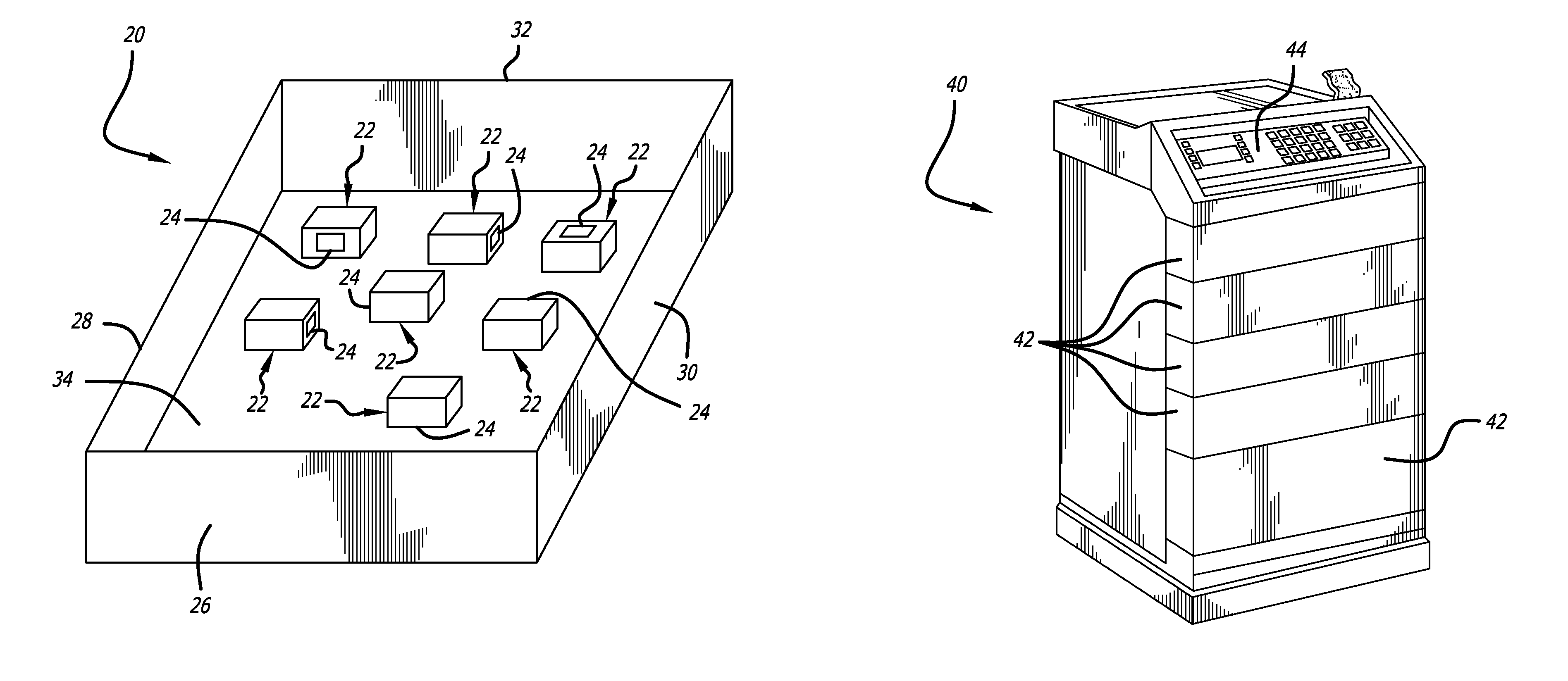
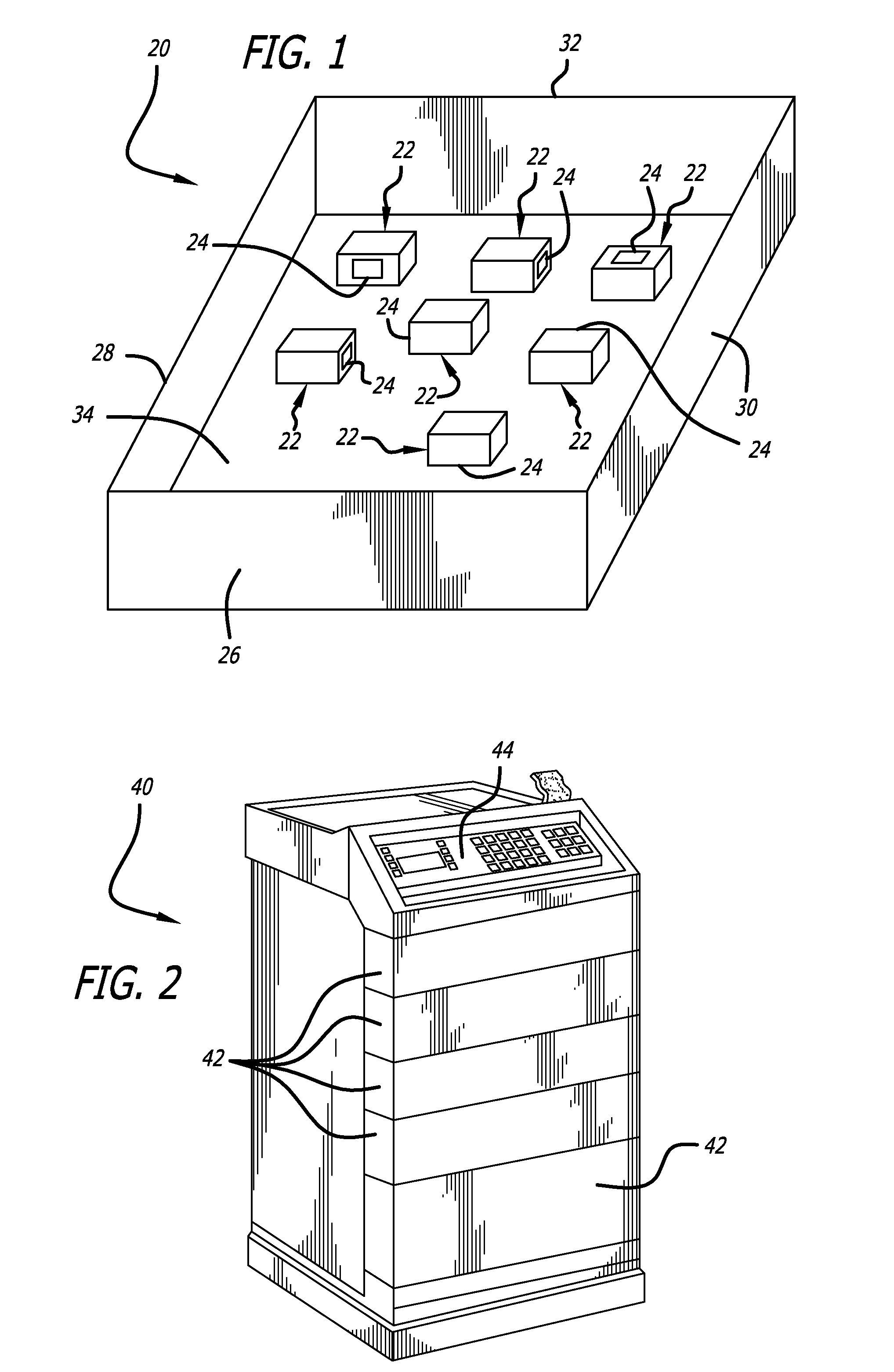
[0052]Referring now in more detail to the exemplary drawings for purposes of illustrating embodiments of the invention, wherein like reference numerals designate corresponding or like elements among the several views, there is shown in FIG. 1 a schematic representation of a partial enclosure 20 in which a plurality of medical articles 22 are stored, each with a respective RFID tag 24 that has a unique identification number. The partial enclosure may comprise a drawer having a front 26, a left side 28, a right side 30, a rear 32, and a bottom 34. These articles are randomly distributed in the drawer with the RFID tags facing in various and random directions.

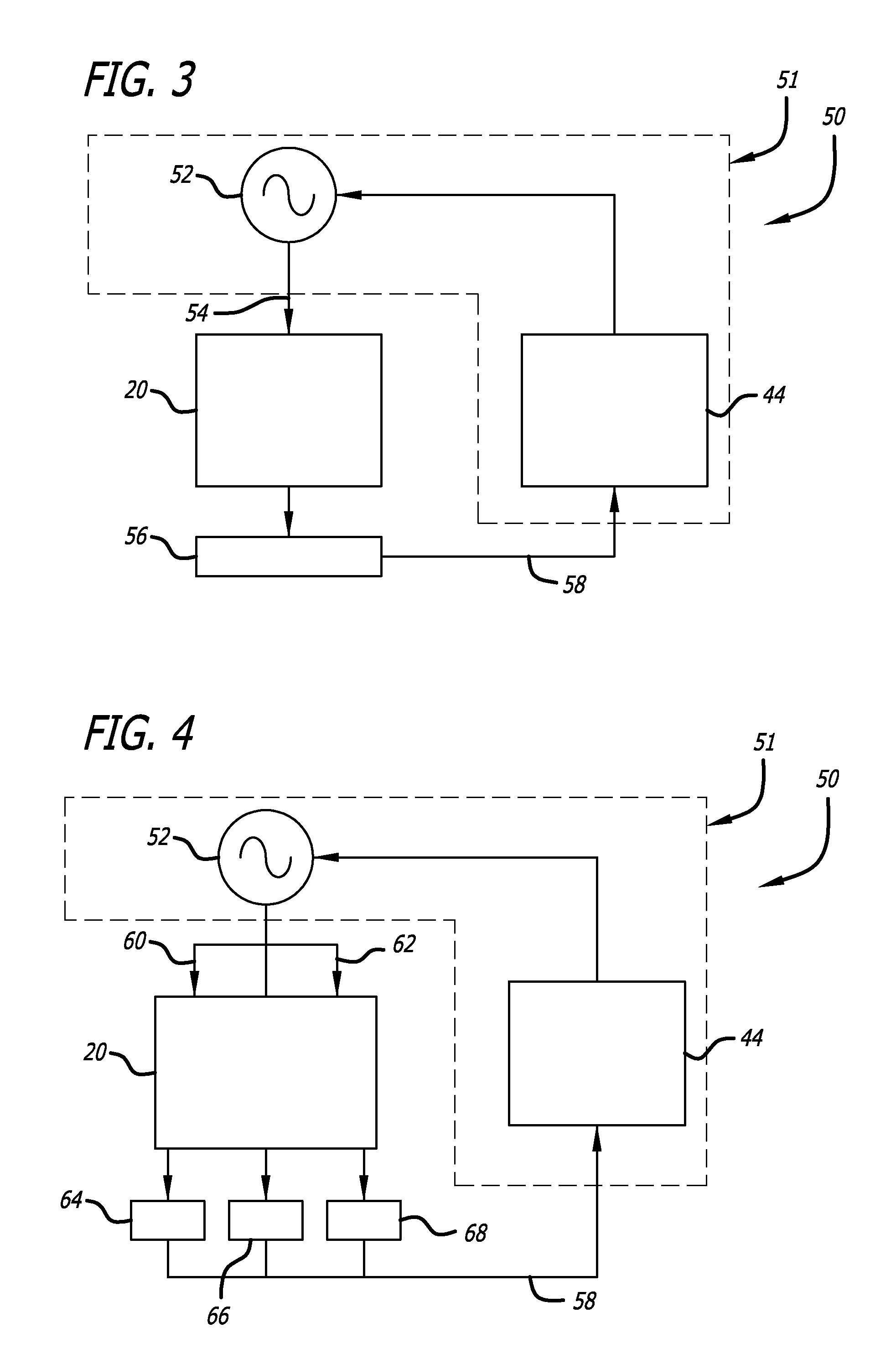
[0053]As used in regard to the embodiments herein, “reader” and “interrogator” refer to a device that may read or write / read. The data capture device is always referred to as a reader or an interrogator regardless of whether it can only read or is also capable of writing. A reader typically contains a radio frequency module (a tra...


PUM


Abstract

An automatic data collection system tracks articles by providing a robust electromagnetic (EM) field within an enclosure in which the articles are stored. Respective data carriers, such as RFID tags, attached to each article respond to the electromagnetic field by transmitting unique data identified with each article. Where the frequency of the EM field coupled to the enclosure differs from the natural resonance frequency of the enclosure, the placement of a probe to couple energy to the enclosure is selected to have the reflected phase of the EM energy from walls equal at the probe location thereby producing a robust EM field to activate and / or detect data carriers.

Description

BACKGROUND[0001]The invention relates generally to the field of automatically collecting data from articles being tracked, and more particularly, to a system and method of establishing a robust electromagnetic field in an enclosure for use in identifying tagged articles.[0002]There are a number of ways of identifying and tracking articles including visually, optically (bar coding, for example), magnetically, RFID, weighing, and others. Where an automatic system for tracking is desired, RFID is a candidate since identification data may be obtained wirelessly. RFID tags have decreased in cost, which has made them even more attractive for such an application.[0003]Radio-frequency identification (“RFID”) is the use of electromagnetic energy (“EM energy”) to stimulate a responsive device (known as an RFID “tag” or transponder) to identify itself and in some cases, provide additionally stored data. RFID tags typically include a semiconductor device having a memory, circuitry, and one or m...

Claims


Application Information

Patent Timeline
Patent Type & Authority Patents(United States)
IPC IPC(8): G08B13/14G16H10/60
CPCG06K7/10366G06K7/10178G06K7/10168G06Q10/087G06Q30/00G16H10/60G16H20/13G16H40/20G16H70/40G06K7/10297G06K17/00G06K19/077G06K19/07749G06Q50/22G16H10/00G16H10/40G16H10/65G16H40/63G16H50/20G16H70/00
Inventor HUSSAIN, SHARIQSHAMBLIN, JEFFREY
Owner MEPS REAL TIME
Why Eureka
Try Eureka