Robotic apparatus implementing collision avoidance scheme and associated methods

a robotic apparatus and collision avoidance technology, applied in the field of robotics, can solve the problems of reducing the efficiency of a manufacturing plant, time-consuming, and disadvantages of the collision avoidance system of otera et al., and achieve the effects of reducing the time it takes to adapt the robotic apparatus, less processing power, and reducing the time it takes to determine potential collisions

Active Publication Date: 2013-02-26
HARRIS CORP
View PDF37 Cites 10 Cited by
  • Summary
  • Abstract
  • Description
  • Claims
  • Application Information

AI Technical Summary

Benefits of technology

[0009]This collision avoidance scheme advantageously allows the first pre-planned actual path of the first robotic manipulator to be reprogrammed without necessitating a reprogramming of the second pre-planned intended path. This may reduce the time it takes to adapt the robotic apparatus to a new application.
[0010]The first controller may generate first drive signals for the first robotic manipulator, and the second controller may determine the potential collision based upon the first drive signals. Additionally or alternatively, the first robotic manipulator may include at least one joint, and a joint sensor cooperating with the at least one joint and the first controller for determining positioning of the at least one joint. The second controller may determine the potential collision based upon the positioning of the at least one joint of the first robotic apparatus. This may allow the determination of potential collisions more accurately and with the use of less processing power than through the use of an image sensor. Of course, the second controller may also determine the potential collision based upon an image sensor or joint position sensor in some embodiments.
[0013]In addition, the second controller may store a geometric model of the first and second robotic manipulators, and the second controller may determine the distance between the second robotic manipulator and the first robotic manipulator based upon the geometric models. The use of geometric models may greatly reduce the processing power consumed in determining potential collisions.
[0015]The second pre-planned intended path may be based upon a sequence of desired velocities. The second controller may move the second robotic manipulator along the dodging path based upon a sequence of dodge velocities to avoid the potential collisions while closely following the sequence of desired velocities of the second pre-planned intended path.
[0016]The second robotic manipulator may comprise at least one joint, and the second controller may determine the sequence of dodge velocities based upon a force on the at least one joint. Additionally or alternatively, the second controller may also determine the sequence of dodge velocities upon kinetic energy of the second robotic manipulator. Determining the sequence of dodge velocities based upon a force or torque on the at least one joint, or based upon kinetic energy of the second robotic manipulator, may advantageously constrain the second robotic manipulator from advancing along a dodge velocity or path that would be potentially damaging to its hardware.

Problems solved by technology

In a manufacturing process that is routinely altered and updated, the collision avoidance system of Otera et al. may be disadvantageous due to the necessary repeated reprogramming thereof.
This collision avoidance system may reduce the efficiency of a manufacturing plant, particularly if there are a variety of differently sized robotic manipulators and the cell sizes of the occupancy grid are sized to accompany the largest robotic manipulators.
Further, since this robotic system operates based upon a model of the workspace, any change to the workplace may require an update of the model, which may be time consuming.
These calculated distances indicate a risk of collision between two adjacent robotic manipulators.
Such a collision avoidance scheme, however, may reduce the efficiency of a manufacturing plant employing the robotic system due to the stopping of robotic manipulators and the associated delays in the manufacturing process.
As explained, these prior approaches may render a manufacturing process employing their respective robotic systems inefficient.
Moreover, robotic systems employing these prior approaches may be difficult and / or costly to adapt to new applications or to the addition of additional robotic manipulators.

Method used


Image

  • Robotic apparatus implementing collision avoidance scheme and associated methods
  • Robotic apparatus implementing collision avoidance scheme and associated methods
  • Robotic apparatus implementing collision avoidance scheme and associated methods

Examples


Embodiment Construction

[0031]The present invention will now be described more fully hereinafter with reference to the accompanying drawings, in which preferred embodiments of the invention are shown. This invention may, however, be embodied in many different forms and should not be construed as limited to the embodiments set forth herein. Rather, these embodiments are provided so that this disclosure will be thorough and complete, and will fully convey the scope of the invention to those skilled in the art. Like numbers refer to like elements throughout, and prime and multiple prime notations are used to indicate similar elements in alternative embodiments.

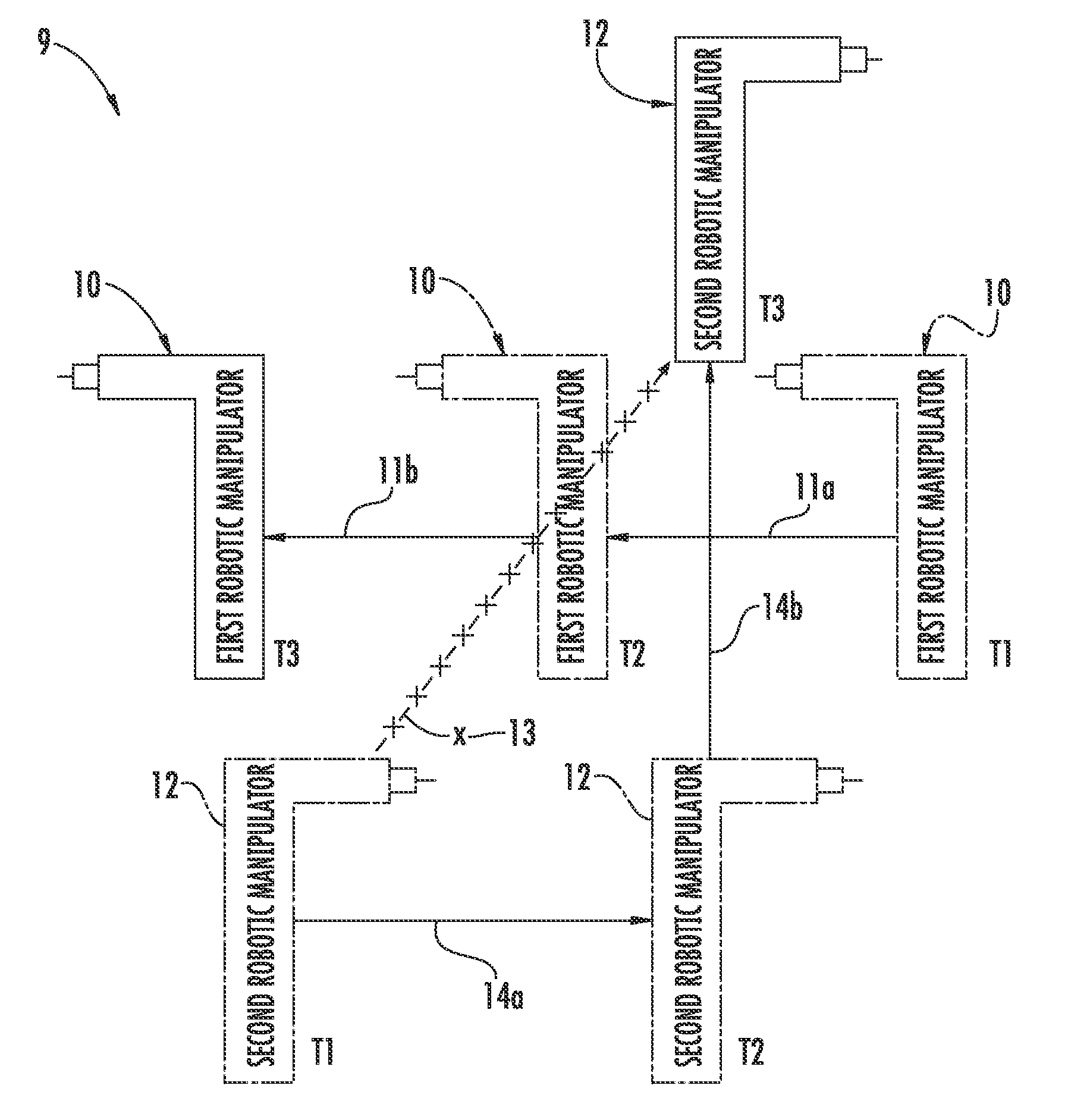
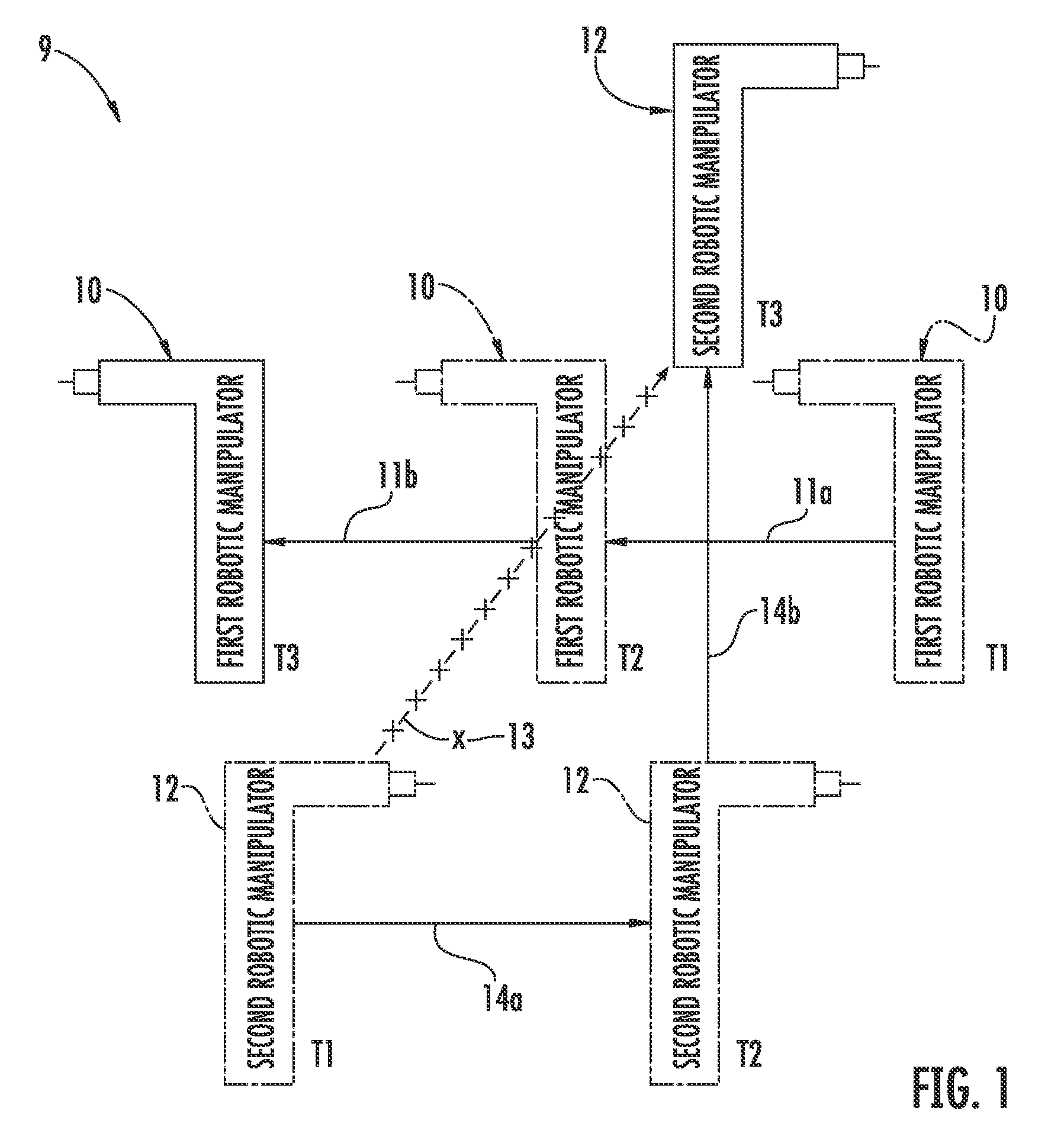
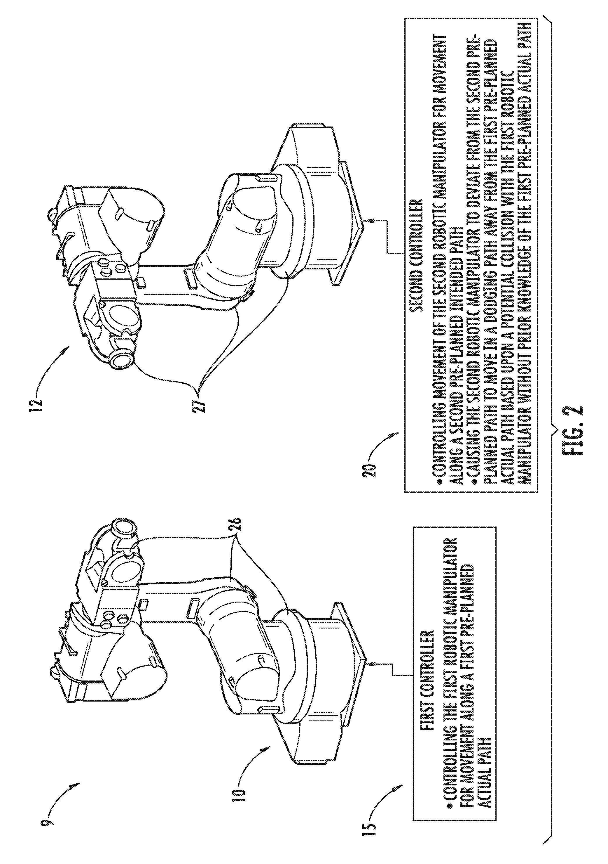
[0032]Referring initially to FIGS. 1-2, a robotic apparatus 9 implementing a collision avoidance scheme is now described. The robotic apparatus 9 includes a first robotic manipulator 10 and a first controller 15 configured to control the first robotic manipulator for movement along a first pre-planned actual path 11a, 11b. In addition, there is a second...


PUM


Abstract

A robotic system implements a collision avoidance scheme and includes a first robotic manipulator and a first controller configured to control the first robotic manipulator for movement along a first pre-planned actual path. A second controller is configured to control movement of a second robotic manipulator for movement along a second pre-planned intended path and deviating therefrom to move in a dodging path away from the first pre-planned actual path based upon determining a potential collision with the first robotic manipulator without prior knowledge of the first pre-planned actual path.

Description

FIELD OF THE INVENTION[0001]The present invention relates to the field of robotics, and, more particularly, to collision avoidance for robotic manipulators and related methods.BACKGROUND OF THE INVENTION[0002]Robotic systems are commonplace in fields such as manufacturing. Indeed, manufacturing plants typically employ robotic systems including numerous robotic manipulators to perform various tasks. To avoid damage to the robotic manipulators, it is helpful to control the robotic manipulators according to a collision avoidance scheme. As such, a variety of collision avoidance schemes for robotic systems have been developed.[0003]Some collision avoidance schemes work by constraining each robotic manipulator to pre-planned collision free paths. For example, one such collision avoidance scheme is disclosed in U.S. Pat. No. 5,204,942 to Otera et al. Such a collision avoidance scheme typically requires reprogramming to accommodate each and every change made to the pre-planned paths of the...

Claims


Application Information

Patent Timeline
Patent Type & Authority Patents(United States)
IPC IPC(8): G05B19/418G06F19/00
CPCB25J9/1676G05B2219/39082G05B2219/40492G05B2219/39091G05B2219/39085Y02P90/02B25J19/02
Inventor BOSSCHER, PAUL MICHAELHEDMAN, DANIEL RYAN
Owner HARRIS CORP
Why Eureka
Try Eureka