Method and system for adaptive modeling and simulation of lossy transmission lines

a transmission line and adaptive modeling technology, applied in the field of adaptive modeling and simulation of lossy transmission lines, can solve the problem that the ideal short-circuited point-to-point connection of physical circuit interconnections such as conductive etches extending between neighboring components of the printed circuit board (pcb) cannot be modeled

Inactive Publication Date: 2013-02-26
CADENCE DESIGN SYST INC
View PDF2 Cites 25 Cited by
  • Summary
  • Abstract
  • Description
  • Claims
  • Application Information

AI Technical Summary

Benefits of technology

[0012]In one exemplary embodiment, the simulation modeling unit of the system includes a scattering parameters formulation unit executable to define a set of frequency-domain modal scattering parameters for the transmission line based on its characteristic frequency-dependent data. A propagation delay extracting unit coupled to the scattering parameters formulation unit is executable to extract from the frequency-domain modal scattering parameters a propagation delay effect of the transmission line, and thereby generate delay-less modal scattering parameter curves for the transmission line. A first decision unit is coupled to the delay extracting unit for making the determination of suitability. The first decision unit defines in response to the frequency-domain delay-less modal scattering parameter curves the suitability of a predefined primary one of the curve approximation options for modeling.
[0013]In another exemplary embodiment, the simulation modeling unit of the system, when configured for the primary curve approximation option, executes a vector fitting unit which generates for each frequency-domain delay-less modal s-parameter curve a partial fraction representation defined by a set of real and complex poles and residues. A state-space model unit coupled to the vector fitting unit thereafter transforms the partial fraction representations of the frequency-domain delay-less modal s-parameter curves to time-domain, thereby generating a time-domain state space model of the transmission line. A passivity enforcement unit coupled to state-space model unit is executed to assess and enforce the passivity of the time-domain state space model of the transmission line. A delay insertion unit coupled to the passivity enforcement unit then executes to insert the propagation delay effect of the transmission line into the time-domain state space model to generate corresponding time-domain state space model formulations. A stamp unit coupled to the delay insertion unit next generates and applies a Modified Nodal Analysis (MNA) stamp based on the time-domain state space model formulations.

Problems solved by technology

In these applications, physical circuit interconnections such as conductive etches extending between neighboring components on a printed circuit board (PCB) cannot be modeled simply as ideal short-circuited point-to-point connections.

Method used


Image

  • Method and system for adaptive modeling and simulation of lossy transmission lines
  • Method and system for adaptive modeling and simulation of lossy transmission lines
  • Method and system for adaptive modeling and simulation of lossy transmission lines

Examples


examples

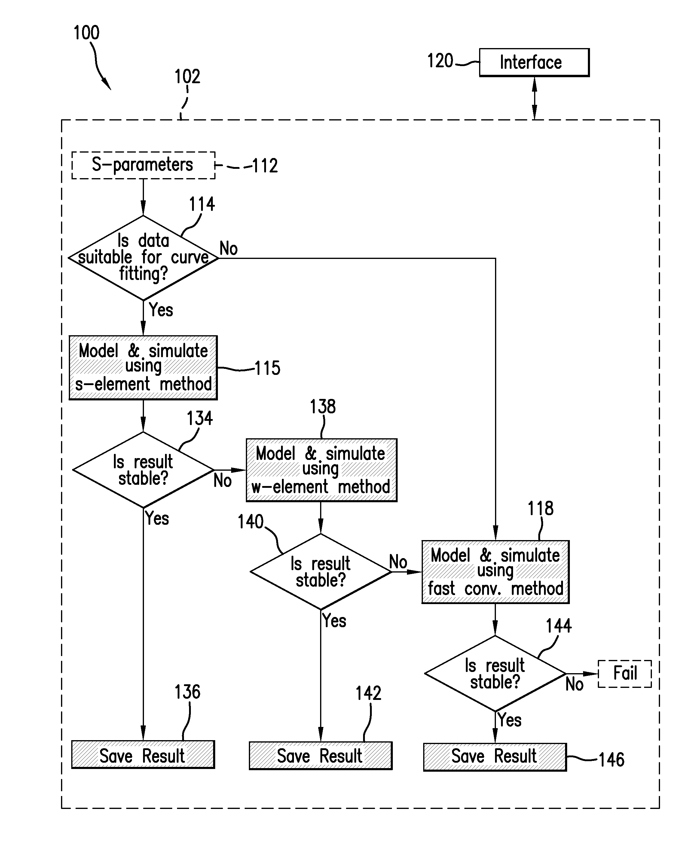
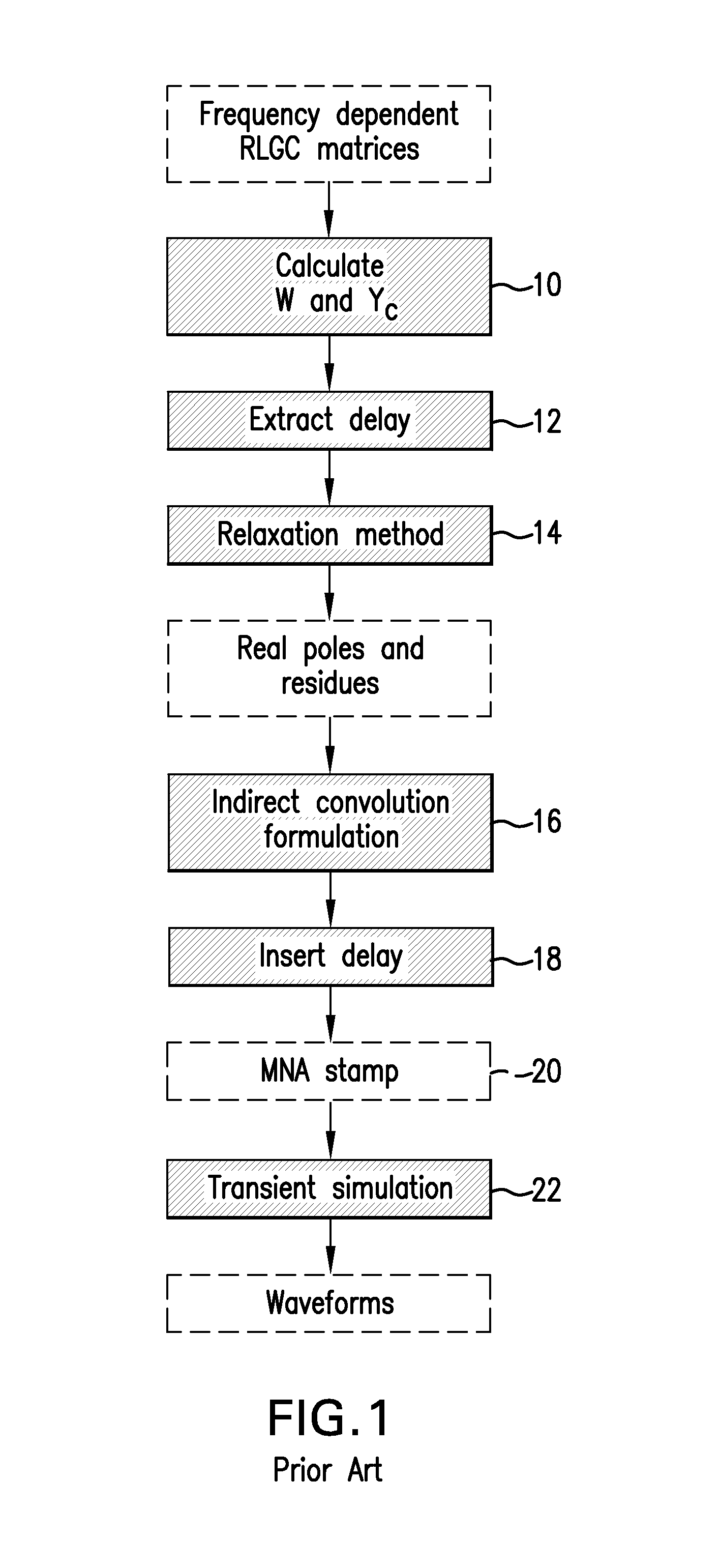
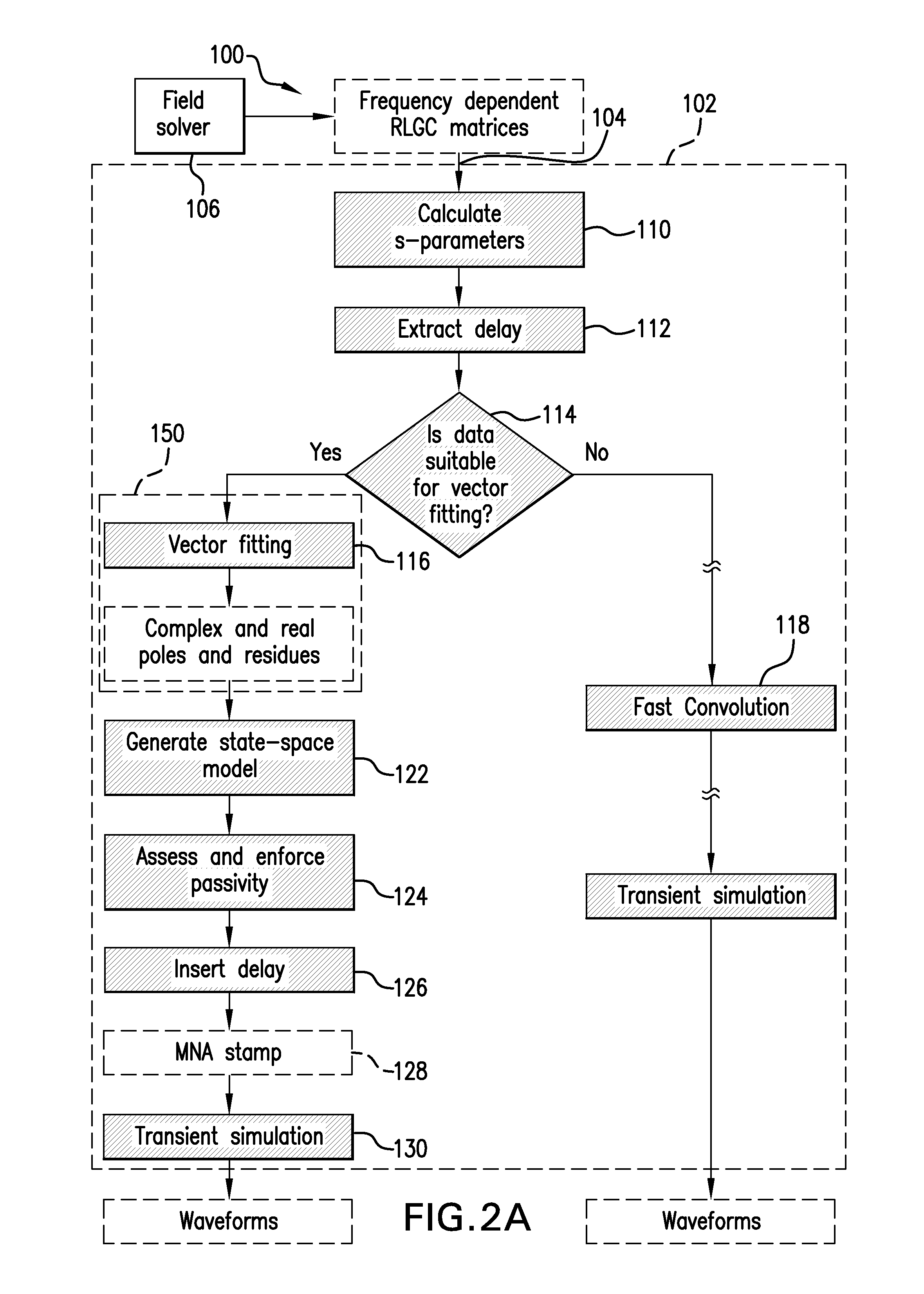
[0154]Numerous modeling / simulation cases have been run to validate the subject method and system. Among them, validation cases were run for the vector fitting approach (initiated by logic unit 116 as shown in FIGS. 2 and 6) to modeling / simulation. An equivalent circuit representing a coupled microstrip line example is schematically illustrated in FIG. 10. In this particular example, the line includes two lines, each 5 inches in length, and is characterized by frequency dependent RLGC data with 50 GHz bandwidth. Transient simulation was performed twice for validation purposes, once with the line modeled in accordance with an embodiment (referenced herein as the ‘s-element’ method) of the present invention disclosed herein, and once with the line modeled in accordance with a known W-element method.

[0155]FIG. 11 illustrates the reference input waveform V1 applied (as represented by the voltage source) to the line's circuit of FIG. 10. The waveform V1 shown defines a pulse having rise a...


PUM


Abstract

A method and system are provided for adaptively modeling and simulating high speed response of a transmission line. A simulation unit maintains a plurality of curve approximation options for modeling the transmission line. The suitability of a predefined primary one of the curve approximation options for modeling is determined based on frequency-domain modal scattering parameters obtained according to frequency-dependent data characterizing the transmission line. One of the options is selectively executed in response to the determination, in order to generate a macromodel of the transmission line. The primary option is executed upon determination of suitability, while a secondary one of the curve approximation options is alternatively executed upon determination of non-suitability. Transient simulation is then executed upon the resulting macromodel of the transmission line.

Description

BACKGROUND OF THE INVENTION[0001]The present invention is directed to a method and system for modeling and simulating transmission lines. More specifically, the method and system serve to adaptively model and simulate lossy multi-conductor transmission lines representing conductive interconnections in a circuit layout, depending on the particularities of a given application. The method and system thereby provide for simulation and evaluation of transmission line transient behavior with an optimal combination of accuracy and, efficiency, even in high speed applications.[0002]With recent advances in IC fabrication technology, and the ongoing development of computer and telecommunication systems, electronic designs operating at higher frequencies are becoming more prevalent. Data rates on the order of multi-Gbit / s, for instance, are not uncommon. In these applications, physical circuit interconnections such as conductive etches extending between neighboring components on a printed circ...

Claims


Application Information

Patent Timeline
Patent Type & Authority Patents(United States)
IPC IPC(8): G06F7/60G06F17/10
CPCG06F17/5036G06F30/367
Inventor AL-HAWARI, FERASTAN, JILINSCHUTT-AINE, JOSE
Owner CADENCE DESIGN SYST INC
Why Eureka
Try Eureka