Power transmission system

a power transmission system and power transmission technology, applied in the direction of transformer/inductance circuit, variable inductance, inductance, etc., can solve the problems of lossy and capacitive power transmission lines or cables, power transmission lines and power transmission cables,

Active Publication Date: 2013-10-15
MAGTECH AS (NO)
View PDF10 Cites 0 Cited by
  • Summary
  • Abstract
  • Description
  • Claims
  • Application Information

AI Technical Summary

Problems solved by technology

There are some technical disadvantages related to different means for transferring electrical power, such as power transmission lines and power transmission cables, especially lossy and capacitive power transmission lines or cables.
Such lines have a too small conductor cross section in relation to the load requirement, and consequently a relatively high resistance and hence high series impedance.
Long cables are also lossy, i.e. they have high series impedance.
Moreover, a lossy line or cable may provide an excessive voltage drop resulting in inadequate voltage levels for the load connected to the line or cable.
Subsea power transmission cables are typically capacitive and lossy.
Due to these properties, the length of such cables is limited.
However, if the load fails or is significantly reduced, the Ferranti effect will cause the cable end voltage to increase, possibly over allowed limits for the cable, penetrators or transformer.
Hence, the load voltage will reach an unacceptable high level which may damage the load.

Method used


Image

  • Power transmission system
  • Power transmission system
  • Power transmission system

Examples


first embodiment

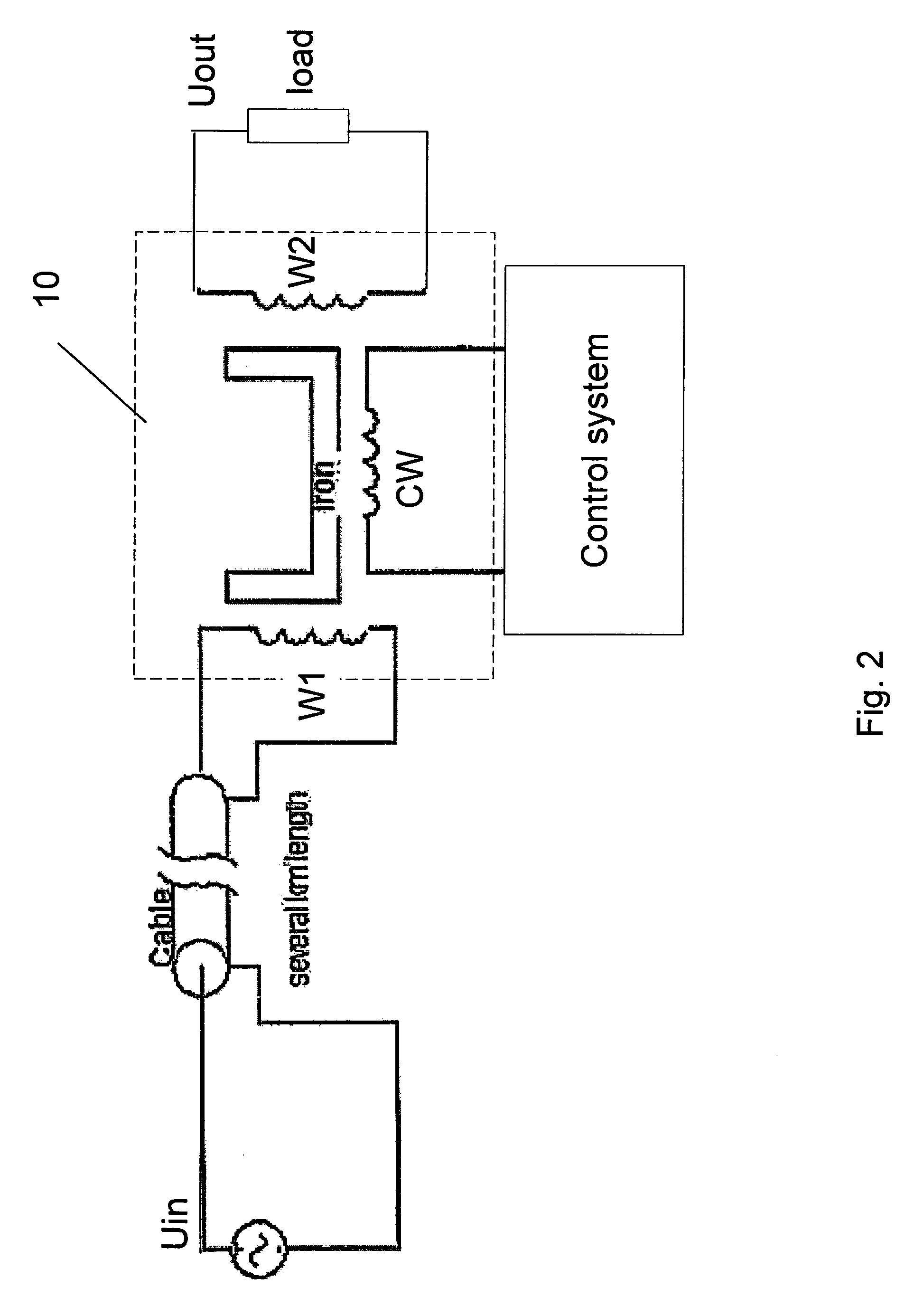
[0030]FIG. 2 illustrates a first embodiment;

second embodiment

[0031]FIG. 3 illustrates a second embodiment;

[0032]FIG. 4 illustrates a plot of the input power as a function of control current.

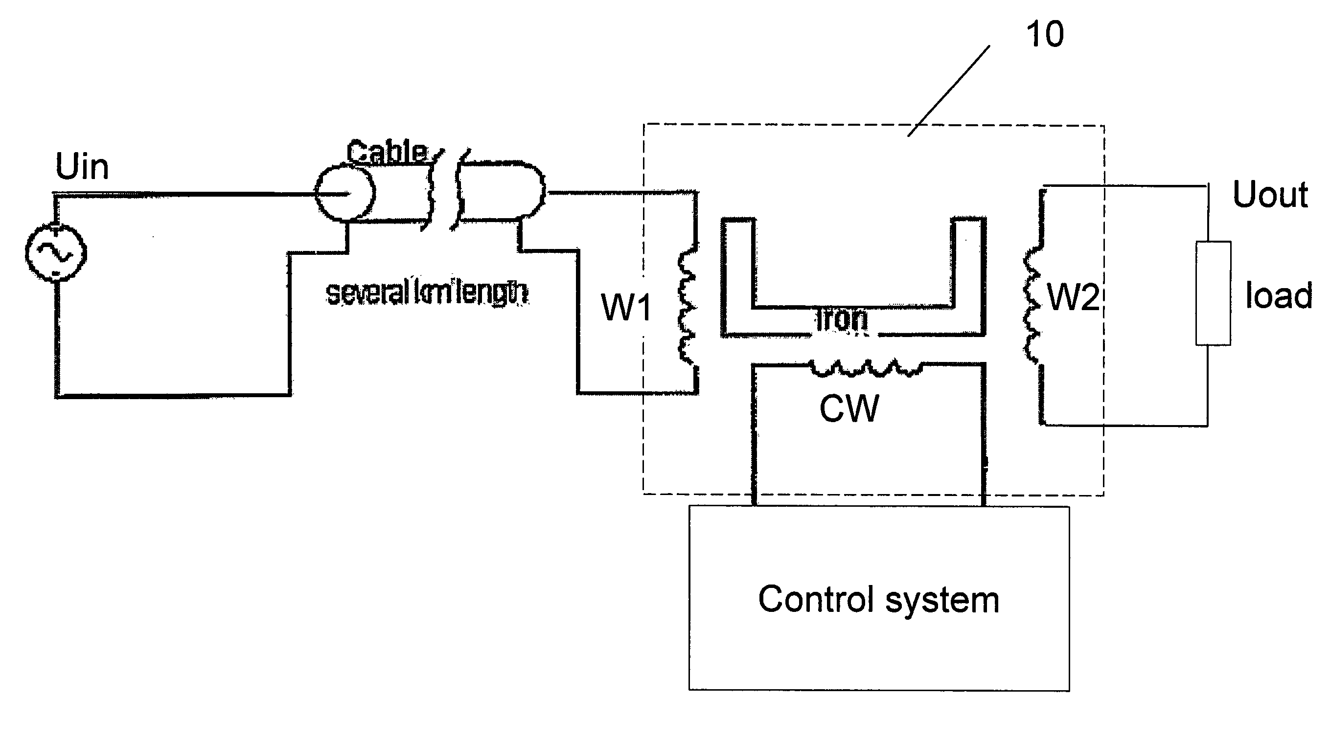
[0033]It is now referred to FIG. 2. Here it is shown a power transmission system for transmitting electrical power from a power source, here referred to as Uin, to a load. The power source may be an AC power with a fixed frequency, or a frequency converter where the frequency may be variable between zero and a nominal frequency.

[0034]The voltage over the load is referred to as Uout. The load may for example be a frequency controlled pump. The load may vary between zero and a nominal value. It should be noted the load in such situations may vary considerably and rapidly, for example in case of gas pockets occurring in the fluid flow being pumped.

[0035]The power transmission system comprises a capacitive and lossy transmission cable. It should be noted that the transmission cable may also be a capacitive and lossy transmission line, i.e. in some situations, ...


PUM

PropertyMeasurementUnit
electrical poweraaaaaaaaaa
magneticaaaaaaaaaa
permeabilityaaaaaaaaaa

Abstract

The invention relates to a power transmission system for transmitting electrical power from a power source to a load. The system comprises a capacitive and lossy transmission line or cable and a transformer device. The transformer device comprises a magnetic core and a first winding wound around a first axis of the magnetic core. The first end of the transmission line or cable is connected to the power source and the second end of the transmission line is connected to the transformer device. A second winding wound around the first axis of the magnetic core, where the second winding is connected to the load. A control winding is wound around a second axis of the magnetic core, where the first axis and the second axis are orthogonal axes to that when the first winding, the second winding and / or the control winding are energized, orthogonal fluxes are generated in the magnetic core. A control system is connected to the control winding for controlling the permeability of the magnet core to automatically provide voltage control of the voltage supplied to the load and control of reactive power supplied to the cable.

Description

FIELD OF THE INVENTION[0001]The present invention relates to a power transmission system for transmitting electrical power from a power source to a load.TECHNICAL BACKGROUND[0002]There are some technical disadvantages related to different means for transferring electrical power, such as power transmission lines and power transmission cables, especially lossy and capacitive power transmission lines or cables.[0003]Undersized power transmission lines for electric power are often referred to as “weak” lines. Such lines have a too small conductor cross section in relation to the load requirement, and consequently a relatively high resistance and hence high series impedance. Long transmission lines may also be capacitive.[0004]Power transmission cables for transferring AC current may only be used up to a certain distance at high voltage levels, since their capacitive properties will prevent power transfer when the cables reaches a certain length. Long cables are also lossy, i.e. they hav...

Claims


Application Information

Patent Timeline
Patent Type & Authority Patents(United States)
IPC IPC(8): H01F27/42
CPCH01F27/38H01F29/14H01F30/16
Inventor JOHANSEN, BJORNAR S.
Owner MAGTECH AS (NO)
Why Eureka
Try Eureka