Aerodynamically enhanced fuel nozzle

a fuel nozzle and aerodynamic enhancement technology, which is applied in the direction of hot gas positive displacement engine plants, combustion processes, lighting and heating apparatus, etc., can solve the problems of photochemical smog problems and production of undesirable combustion products

Active Publication Date: 2013-03-05
GENERAL ELECTRIC CO
View PDF25 Cites 45 Cited by
  • Summary
  • Abstract
  • Description
  • Claims
  • Application Information

AI Technical Summary

Problems solved by technology

Aircraft gas turbine engine staged combustion systems have been developed to limit the production of undesirable combustion product components such as oxides of nitrogen (NOx), unburned hydrocarbons (HC), and carbon monoxide (CO) particularly in the vicinity of airports, where they contribute to urban photochemical smog problems.

Method used


Image

  • Aerodynamically enhanced fuel nozzle
  • Aerodynamically enhanced fuel nozzle
  • Aerodynamically enhanced fuel nozzle

Examples


Embodiment Construction

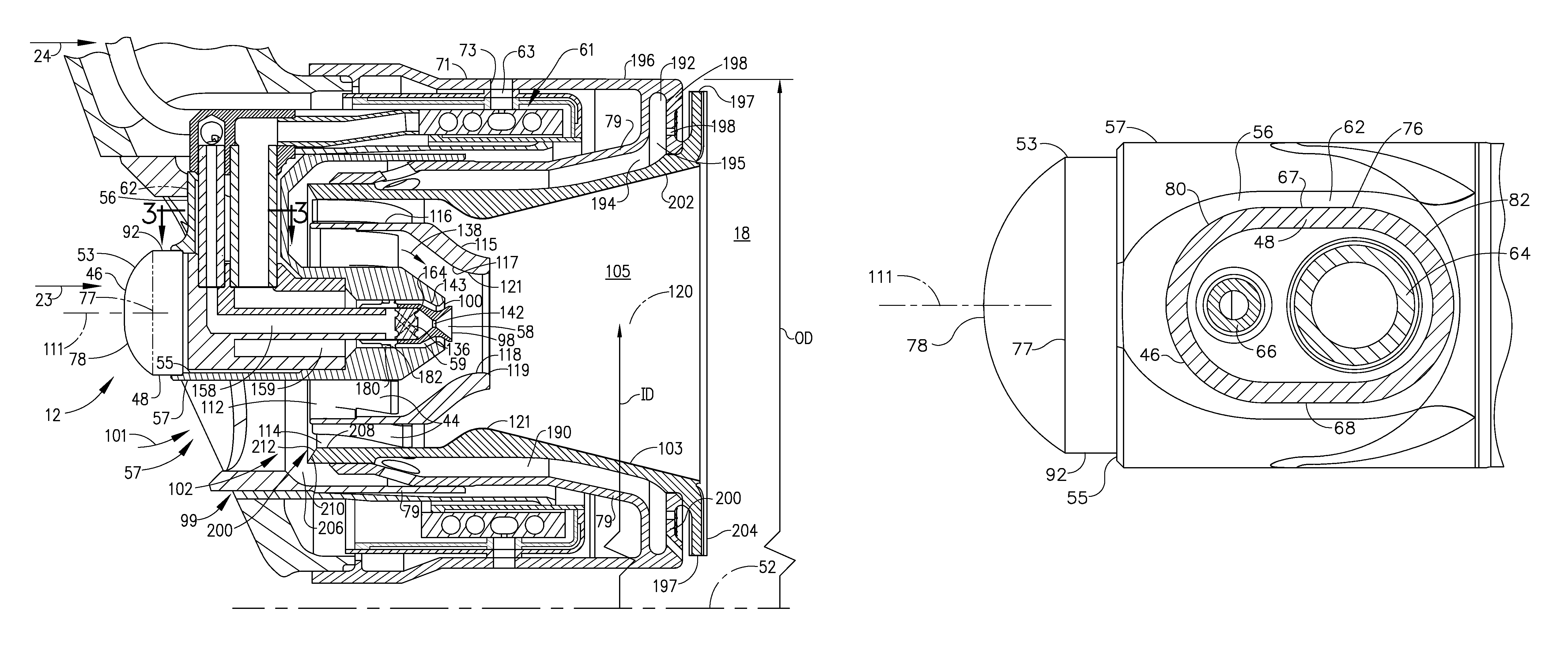
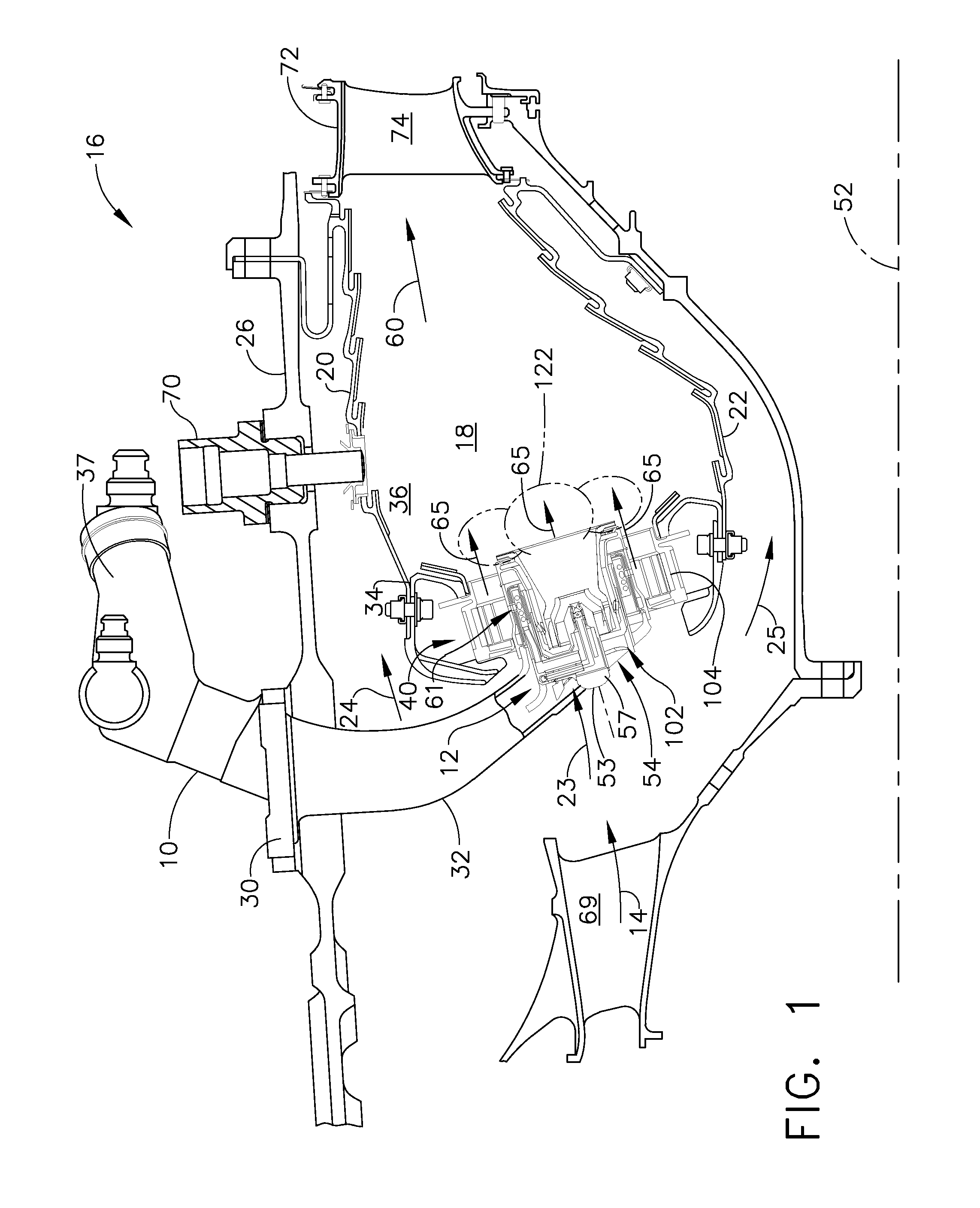
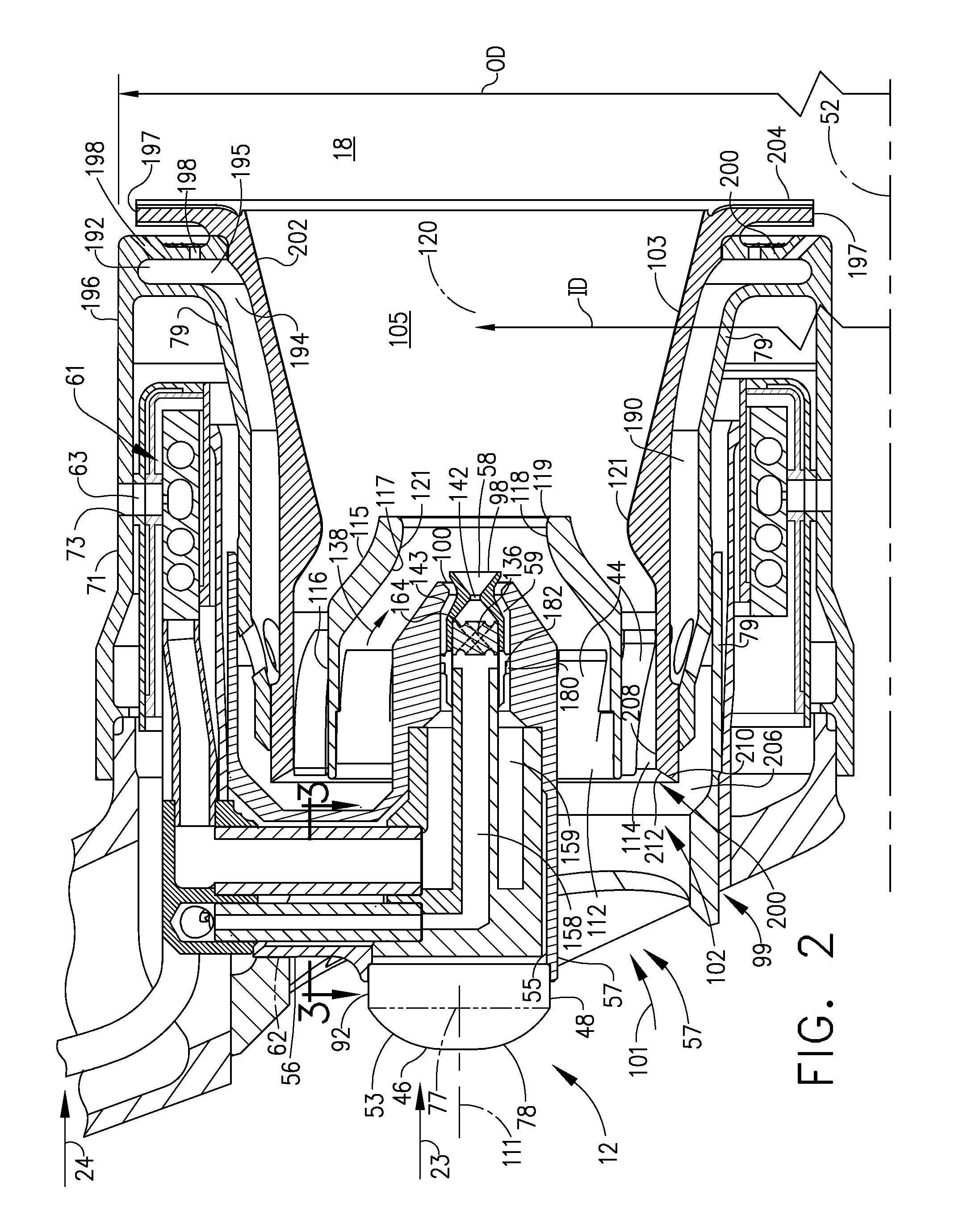
[0026]Illustrated in FIG. 1 is an exemplary embodiment of a combustor 16 including a combustion zone 18 defined between and by annular radially outer and inner liners 20, 22, respectively circumscribed about an engine centerline 52. The outer and inner liners 20, 22 are located radially inwardly of an annular combustor casing 26 which extends circumferentially around outer and inner liners 20, 22. The combustor 16 also includes an annular dome 34 mounted upstream of the combustion zone 18 and attached to the outer and inner liners 20, 22. The dome 34 defines an upstream end 36 of the combustion zone 18 and a plurality of mixer assemblies 40 (only one is illustrated) are spaced circumferentially around the dome 34. Each mixer assembly 40 includes a main mixer 104 mounted in the dome 34 and a pilot mixer 102.

[0027]The combustor 16 receives an annular stream of pressurized compressor discharge air 14 from a high pressure compressor discharge outlet 69 at what is referred to as CDP air ...


PUM


Abstract

A gas turbine engine fuel nozzle assembly includes a pilot fuel injector tip substantially centered about a centerline axis in an annular pilot inlet to a pilot mixer. A cross over arm extends across inlet to tip. Arm includes an arm fairing surrounding at least one fuel transfer tube to tip. A pilot nose cap is at an upstream end of tip. At least one of the cross over arm and the pilot nose cap includes a rounded forebody followed by a straight afterbody. Rounded forebody of pilot nose cap includes a substantially rounded dome extending forwardly from a rounded nose base and straight afterbody includes a substantially cylindrical nose afterbody parallel to a pilot nose centerline normal to nose base. An arm fairing surrounding fuel transfer tubes to tip includes rounded leading and trailing edges and a rectangular middle section therebetween having flat first and second sides.

Description

BACKGROUND OF THE INVENTION[0001]1. Field of the Invention[0002]The present invention relates to gas turbine engine fuel nozzles and, more particularly, to such fuel nozzles having pilot fuel injector tips containing pilot fuel nozzles.[0003]2. Description of Related Art[0004]Aircraft gas turbine engine staged combustion systems have been developed to limit the production of undesirable combustion product components such as oxides of nitrogen (NOx), unburned hydrocarbons (HC), and carbon monoxide (CO) particularly in the vicinity of airports, where they contribute to urban photochemical smog problems. Gas turbine engines also are designed to be fuel efficient and have a low cost of operation. Other factors that influence combustor design are the desires of users of gas turbine engines for efficient, low cost operation, which translates into a need for reduced fuel consumption while at the same time maintaining or even increasing engine output. As a consequence, important design crit...

Claims


Application Information

Patent Timeline
Patent Type & Authority Patents(United States)
IPC IPC(8): F02C1/00
CPCF23R3/28F23R3/34F23R3/60
Inventor PATEL, NAYAN VINODBHAIBENJAMIN, MICHAEL ANTHONYTHOMSEN, DUANE DOUGLASMANCINI, ALFRED ALBERT
Owner GENERAL ELECTRIC CO
Why Eureka
Try Eureka