
Self deploying solar array

a solar array and self-distribution technology, applied in the direction of pv power plants, transportation and packaging, cosmonautic vehicles, etc., can solve the problems of flexible solar arrays that have also been used, and achieve the effect of facilitating storage as a roll

Active Publication Date: 2013-03-05
COMPOSITE TECH DEV
View PDF51 Cites 29 Cited by
  • Summary
  • Abstract
  • Description
  • Claims
  • Application Information

AI Technical Summary

Benefits of technology

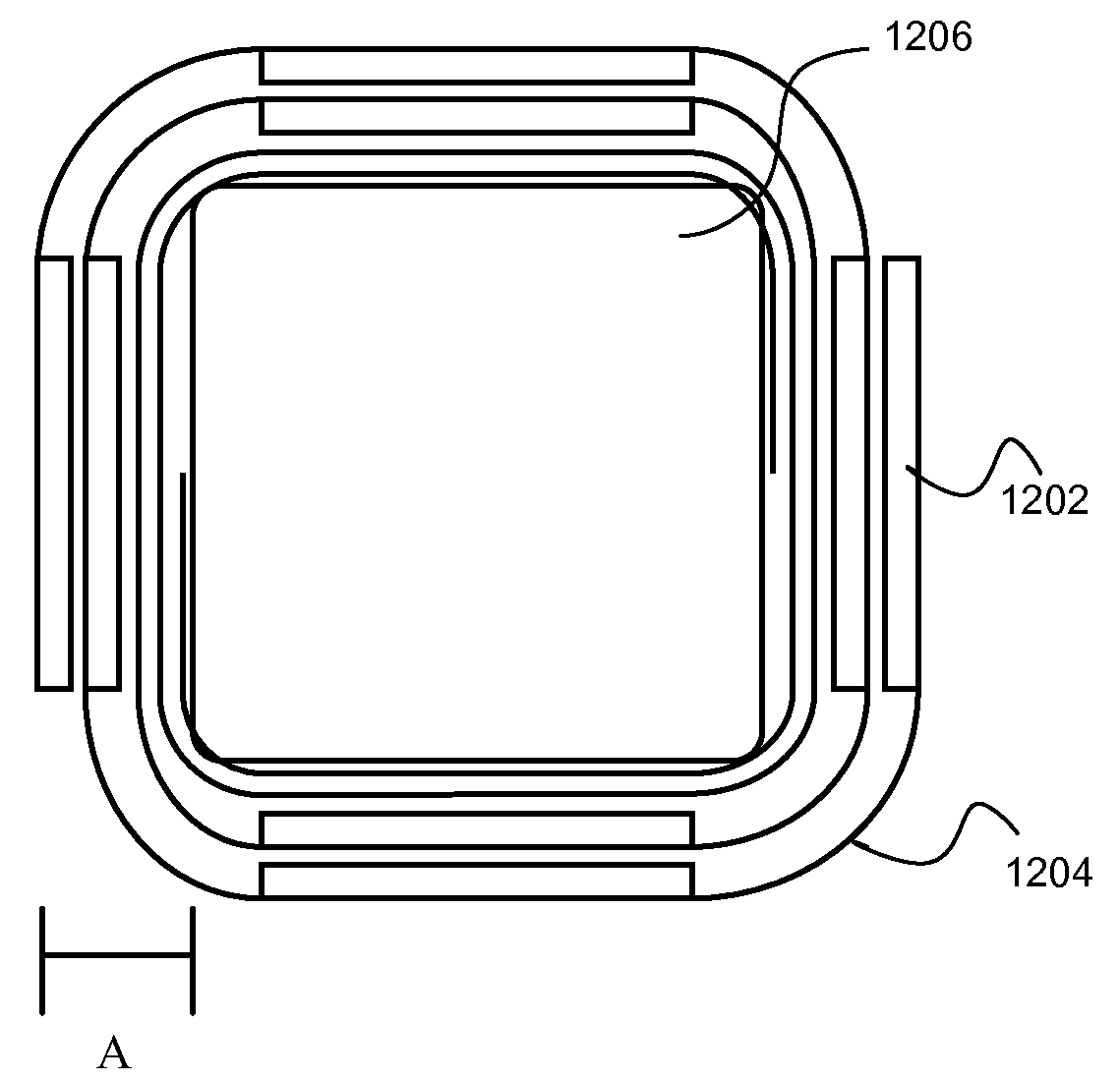
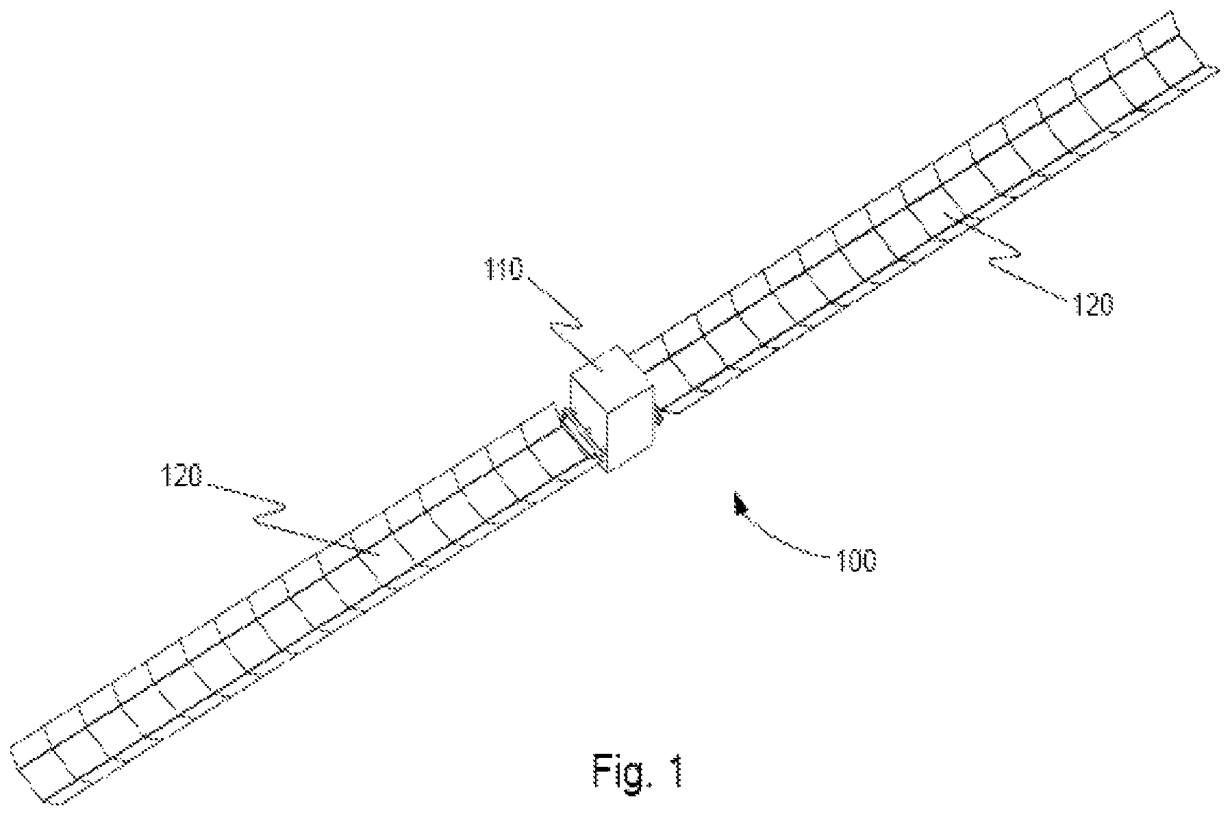
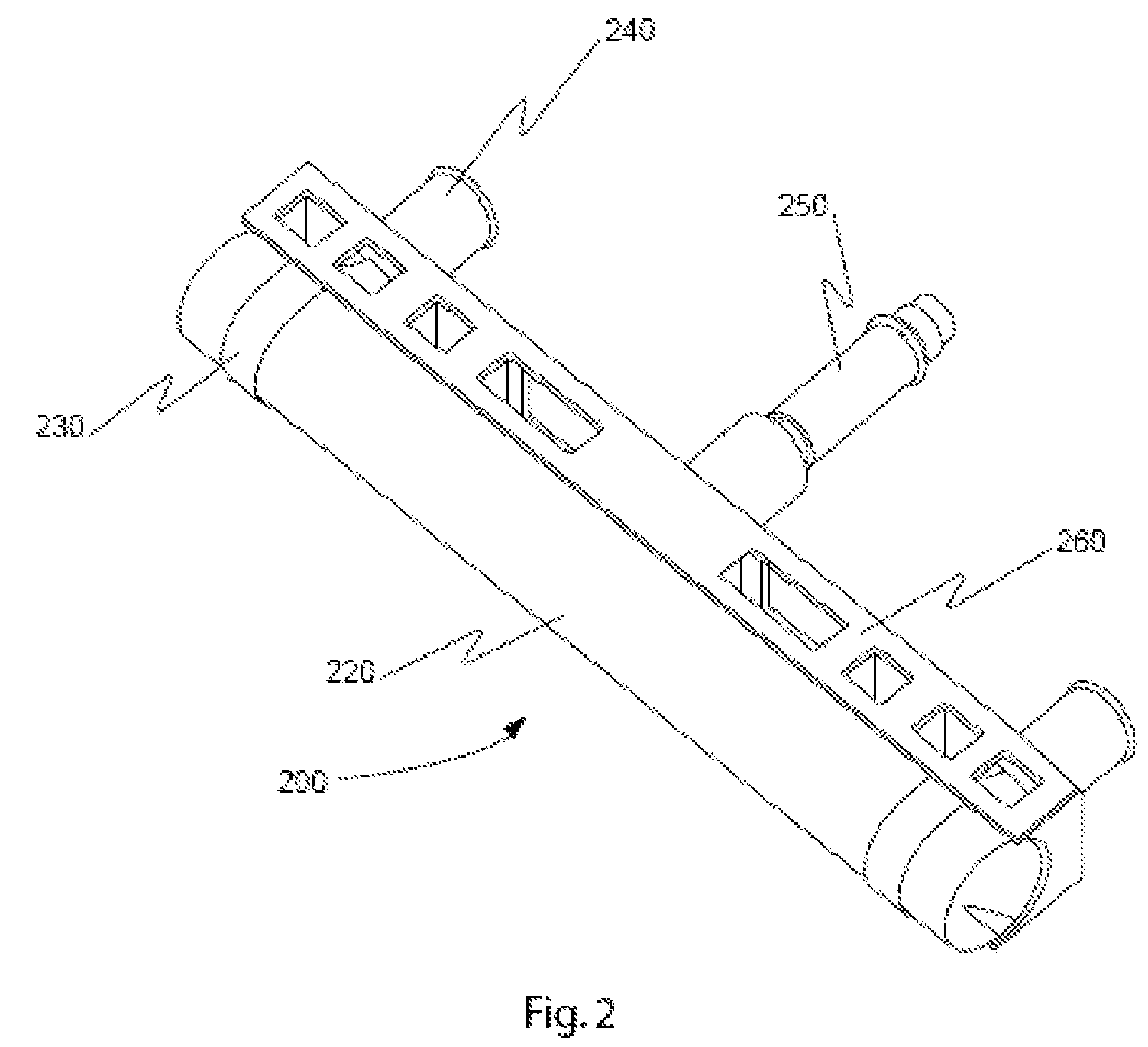
The patent describes a deployable structure that can be easily stored and deployed for use with a satellite. The structure includes a flat panel that can be positioned flat against the satellite when stowed. When deployed, a roll-out tubular member with a flat cross-section allows for easy wrapping around the satellite. Additionally, a flexible solar array sheet can be easily stowed and deployed as a roll for use with the satellite. The technical effects of this design include easy storage and deployment, efficient use of space, and reliable power supply.

Problems solved by technology

Flexible solar arrays have also been used, but have been limited to thin-film arrays packaged in a long roll or pleated stack that is deployed using a separate boom or booms.

Method used


Image

  • Self deploying solar array
  • Self deploying solar array
  • Self deploying solar array

Examples


Embodiment Construction

[0033]Spacecraft are limited in power, stowed volume, and mass available to meet requirements. These parameters are traded against each other as well as overall cost in spacecraft design. More efficient solar array packaging and mass would allow spacecraft to have more power on orbit or the same power for less mass and stowed volume. Additional power could be used, for example, to increase services for RF communications, provide power for electric propulsion, or increase the science capability of exploratory spacecraft. Similarly, additional stowed volume could be used, for example, for additional antennas for RF communications or larger science instruments. Also, a simpler solar array design could be fabricated and tested for a lower cost. Because of the extremely constrained nature of spacecraft design and because nearly all spacecraft require solar arrays for power, solar arrays with greater mass and volume efficiency could be used to increase the capability or decrease the cost ...


PUM


Abstract

A deployable structure that may include a slit-tube longeron and a flat panel coupled with the slit-tube longeron. The slit-tube longeron may include a tubular member having a slit that runs along the longitudinal length of the slit-tube longeron. The deployable structure may be configured to couple with a satellite. And the deployable structure may be configured to transform between a stowed state and a deployed state where the tubular member is substantially straight when the deployable structure is in the deployed state, and the tubular member is wrapped around the satellite when the deployable structure is in the stowed state.

Description

CROSS-REFERENCES TO RELATED APPLICATIONS[0001]This application is a continuation-in-part, and claims the benefit, of co-pending, commonly assigned U.S. patent application Ser. No. 12 / 873,615, filed Sep. 1, 2010, entitled “Large-Scale Deployable Solar Array,” which is a continuation of U.S. patent application Ser. No. 11 / 695,163, filed Apr. 2, 2007, entitled “Large-Scale Deployable Solar Array,” which is a non-provisional of and claims the benefit of co-pending, commonly assigned, U.S. Provisional Application No. 60 / 788,449, filed on Mar. 31, 2006, entitled “Large-Scale Deployable Solar Array,” the entirety of which is herein incorporated by reference for all purposes. This application is also a non-provisional of and claims the benefit of U.S. Provisional Application No. 61 / 310,205, filed on Mar. 3, 2010, entitled “Collapsible Structures,” the entirety of which is herein incorporated by reference for all purposes.STATEMENT AS TO RIGHTS TO INVENTIONS MADE UNDER FEDERALLY SPONSORED RE...

Claims


Application Information

Patent Timeline
Patent Type & Authority Patents(United States)
IPC IPC(8): B64G1/22
CPCB64G1/222B64G1/443H02S30/20H02S20/00Y02E10/50H02S20/30B64G1/2225B64G1/2222
Inventor TAYLOR, ROBERTKELLER, PHILIP N.MALLICK, KAUSHIKTURSE, DANAHULSE, MICHAEL J.
Owner COMPOSITE TECH DEV
Learn More