Method for measuring shear wavespeed in an isotropic plate

a shear wave speed and isotropic plate technology, applied in the direction of instruments, spectral/fourier analysis, material analysis, etc., can solve the problem of not having the capability to separate various wave types and their associated response levels, and achieve accurate estimation

Active Publication Date: 2013-03-05
THE UNITED STATES OF AMERICA AS REPRESENTED BY THE SECRETARY OF THE NAVY
View PDF7 Cites 7 Cited by
  • Summary
  • Abstract
  • Description
  • Claims
  • Application Information

AI Technical Summary

Benefits of technology

[0013]Shaker tests are mechanical tests that are used to excite motion in different types of structures. Typically, some form of measurement is concurrently taken during the test so that data can be analyzed. Laser velocimeters that measure the velocity of the structure and accelerometers that measure the acceleration are employed to collect the data. Once this is accomplished, insight into the structures response due to varying mechanical loading conditions can be determined. Testing simple structures such as plates, beams and shells is useful because analytical solutions of their responses have been derived and direct comparison between predicted response and actual response can be achieved.
[0014]The shear wavespeed is measured in a plate in the region where dilatational and shear wavelengths begin to approach the plate thickness, i.e., fully elastic dynamic behavior. The plate is mechanically excited by a point force at a fixed frequency while simultaneously measuring the normal velocity of the plate across its entire surface. These spatial domain measurements are transferred into a wavevector two-wavenumber (kx,ky) domain by means of two Fourier transforms. Individual waves are identified in this domain, and the resulting wave propagation wavenumbers are accurately estimated. Once they are measured, the estimated wavenumbers are inserted into a Newton-Raphson iterative solver applied to the theoretical Rayleigh-Lamb equations for the propagation of waves in a plate with traction-free boundary conditions. Results of estimates of the squares of the shear wavenumbers are thus obtained, allowing for calculations of the shear wavespeed.

Problems solved by technology

Few wavespeed estimation techniques have been developed for general plates and beams.
Transfer function methods that measure one output (at a single location) versus a fixed input do not have the capability to separate various wave types and their associated response levels.

Method used


Image

  • Method for measuring shear wavespeed in an isotropic plate
  • Method for measuring shear wavespeed in an isotropic plate
  • Method for measuring shear wavespeed in an isotropic plate

Examples


Embodiment Construction

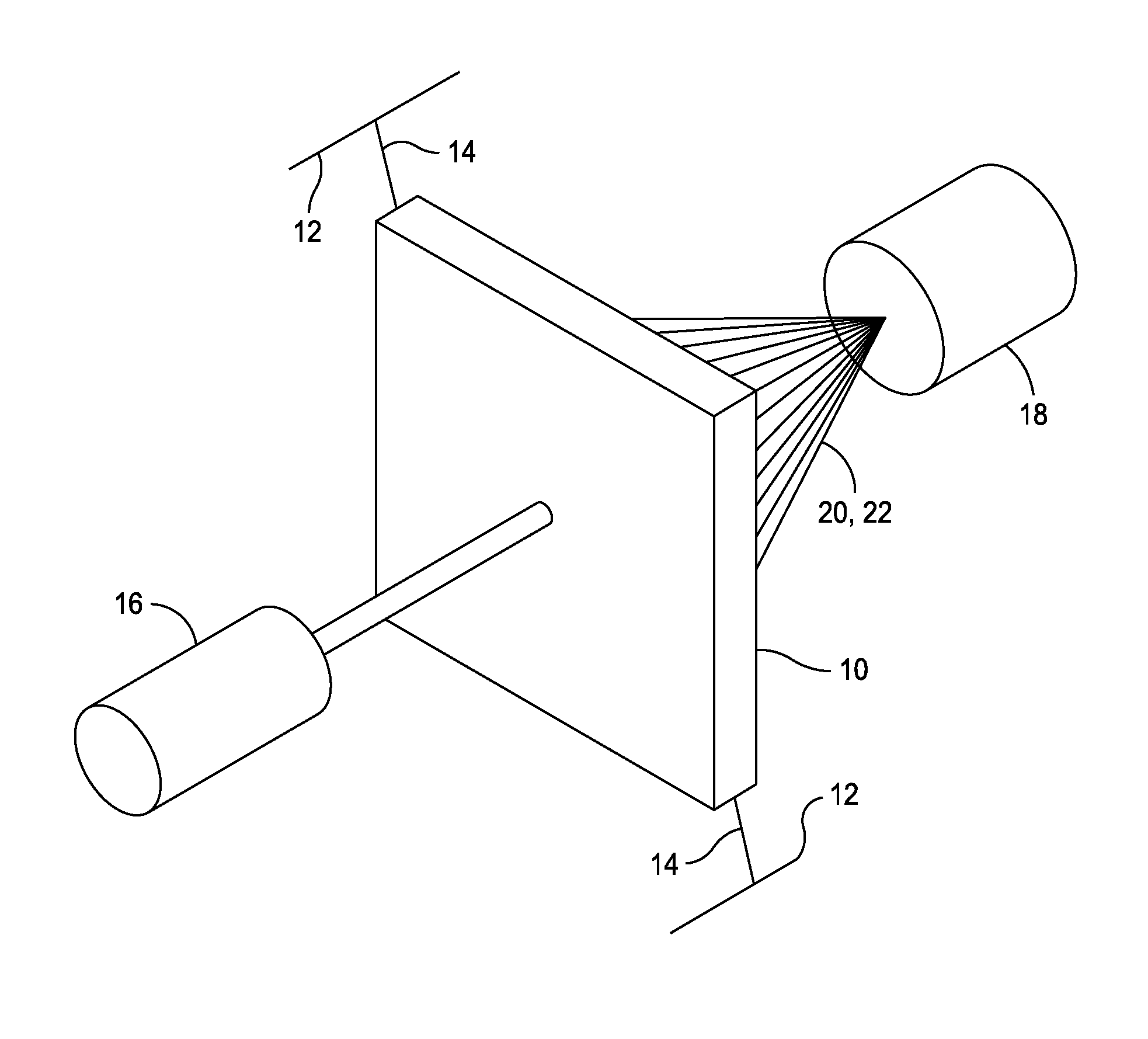
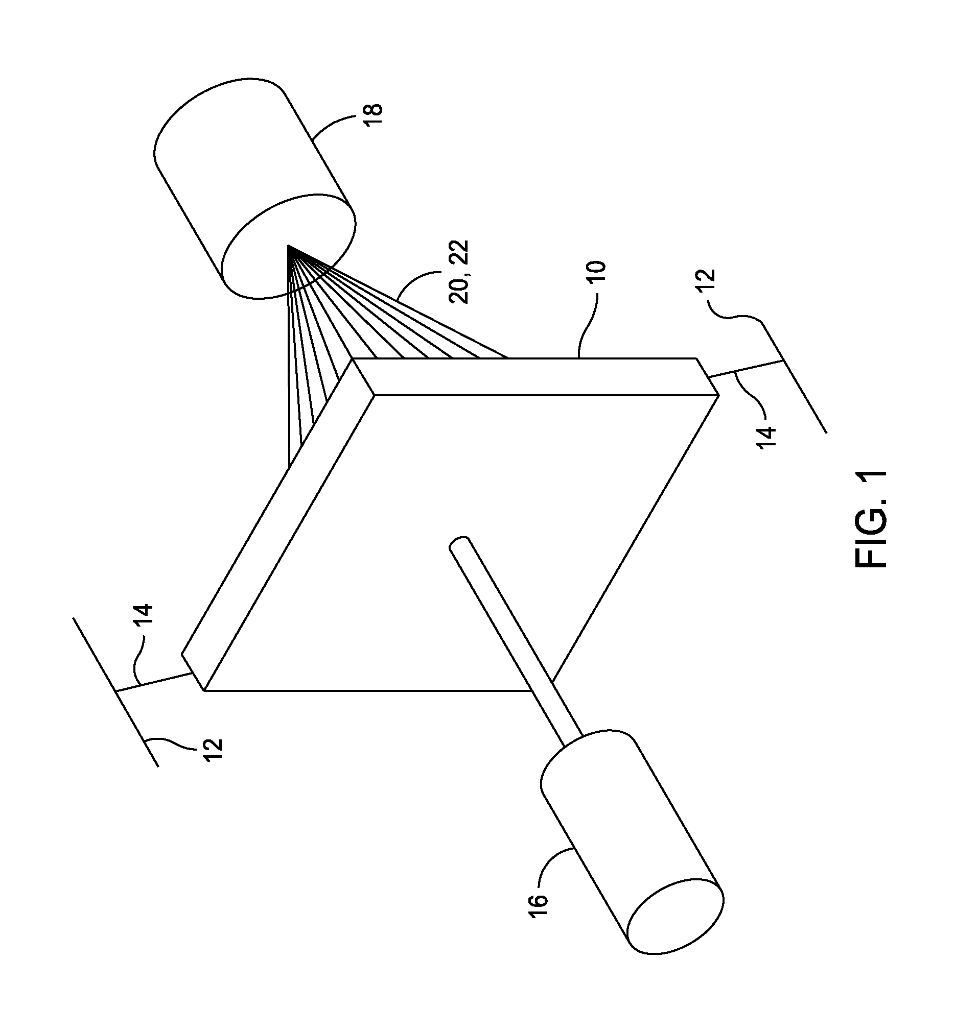
[0026]A possible experimental setup for the present method is given in FIG. 1. A test plate 10 is joined to a structure or fixed frame 12 by resilient cords 14. Two corner supports are shown in the drawing, but more supports could be present. Plate 10 is preferably around 1 inch thick; however, almost any thickness can be used. Thinner plates lose vibration modes. Thicker plates lose vibration through losses in lossy materials such as resilient materials like plastic and rubber. Resilient cords 14 can be any elastic cord or spring providing sufficient elasticity to avoid affecting plate 10 vibration. A shaker 16 is joined to the center of plate 10. Shaker 16 can be an electromagnetic or mechanical shaker that is capable supporting the frequencies of interest. Shaker 16 should be joined to plate 10 at a single point. A laser vibrometer 18 is positioned on the opposite side of plate 10 allowing measurement of vibrations from the entire surface of plate 10. Vibrometer 18 provides a bea...


PUM


Abstract

Using a mechanical shaker test the shear wavespeed in a plate is estimated by applying a cyclical point force to the plate, measuring normal velocity of waves caused by the force, transforming temporal domain measurements with a Fourier transform into a frequency domain, transforming spatial domain measurements into a {kx,ky} wavevector domain spectra using Fourier transforms, determining propagation wavenumbers for given Lamb waves from peaks within the {kx,ky} spectra, and determining shear wavespeed by applying a Newton-Raphson gradient method using the propagation wavenumbers to Raleigh-Lamb dispersion curve equations.

Description

STATEMENT OF GOVERNMENT INTEREST[0001]The invention described herein may be manufactured and used by or for the Government of the United States of America for governmental purposes without the payment of any royalties thereon or therefor.CROSS REFERENCE TO OTHER PATENT APPLICATIONS[0002]None.BACKGROUND OF THE INVENTION[0003](1) Field of the Invention[0004]The present invention is generally directed towards a method to measure the shear wavespeed in an isotropic plate. More specifically, the invention is directed towards a method to estimate the shear wavespeed of a plate shaped test specimen using a mechanical shaker test.[0005](2) Description of the Prior Art[0006]The shear wave, S-wave or secondary wave, is one of the two main types of elastic body waves, a type of seismic wave, that moves through the body of an object, unlike surface waves. The shear wave moves as a shear or transverse wave, so motion is perpendicular or normal to the direction of wave propagation. The shear wave...

Claims


Application Information

Patent Timeline
Patent Type & Authority Patents(United States)
IPC IPC(8): G01R23/00G01R23/16
CPCG01N29/045G01N2203/0005G01N2203/0007G01N2291/0422G01N2203/0688G01N2291/02827G01N2203/0658
Inventor HULL, ANDREW J.CRAY, BENJAMIN A.
Owner THE UNITED STATES OF AMERICA AS REPRESENTED BY THE SECRETARY OF THE NAVY
Why Eureka
Try Eureka